Checking clearance between piston rings and pis-
ton ring grooves in piston
This check is to be made with new piston rings, as shown in figure
32, by inserting the piston ring into the groove and then the blade
of no. 5.9030.270.0 thickness gauge. Refer to specifications table
for maximum clearance allowance.
If the clearance measured exceeds the maximum allowance,
piston shall be replaced.
Installing piston rings
During cylinder assembly perform a proper orientation of the first
piston ring so that its cut be moved by 60° from the gudgeon pin
axis.
The other piston rings should be inserted with their cuts moved by
120° from each other.
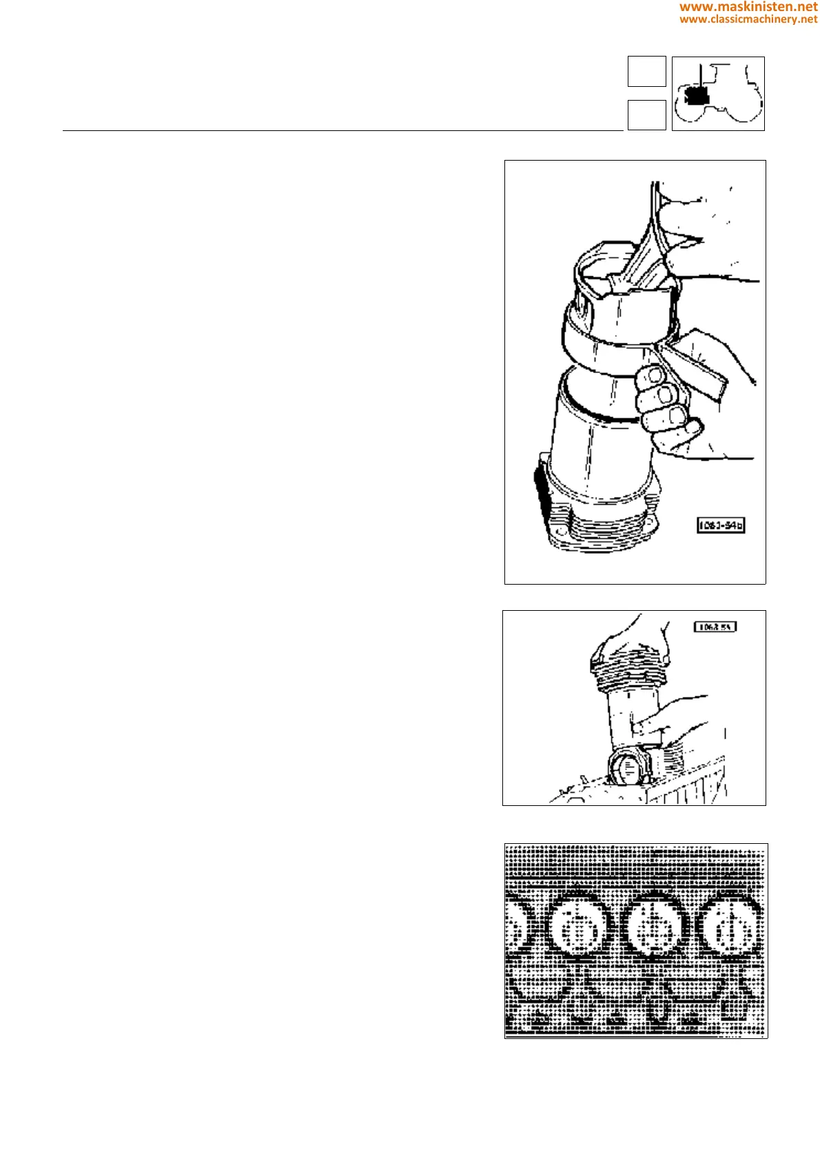
Installing pistons into cylinders
Use no. 5.9030.654.0 ring clamping band as shown in figure 34
to install piston into the cylinder.
Afterwards insert piston and cylinder assemblies into the cylinder
block.
NOTE - Pistons can be taken without removing the crankshaft,
just withdrawing along with the connecting rods directly from the
cylinders after removing both cylinder heads and connecting rod
caps.
Before installing the cylinder liners, fit the O-ring seals code
2.1539.130.0.
The connecting rod-piston assembly must be assembled with the
piston crown recess oriented towards the tappets (Fig. 36).
The big-end caps must be fitted so that the punched number
appears on the same side as the number on the connecting rod.
Fig. 34 - Installing piston into cylinder.
Fig. 35 - Installing piston and cylinder assembly.
Fig. 36 - Correct orientation of piston and con-rod
assembly.
engine
crankshaft
12
1
39
www.maskinisten.net
www.classicmachinery.net