Cleaning cylinder heads
Clean the cylinder heads thoroughly by removing any coking
inside both exhaust and intake ducts. Also clean cylinder head
cooling fins carefully.
Checking valve seats
First descale and clean valve seats and then inspect for either
pitting or corrosion in the valve contact area, otherwise a new
grinding (if light wear is found) or a replacement shall be provided.
To install new valve seat inserts operate as follows:
chill the valve seat inserts in liquid nitrogen for easier installation
in the cylinder head by running fit.
Valve seat inserts are supplied as finished parts and do not require
any further machining. On installation avoid knocking on the valve
seats to prevent distortion.
NOTE - If no liquid nitrogen is available for valve seat insert chilling
before installation, it is also possible to heat up the cylinder head
to a temperature of 200° to 300°C.
Checking valves
Descale the valves with the special brush.
Make sure the valve seat is thoroughly intact, otherwise replace.
Check the valve stem for deformation, be sure the stem outside
diameter is not below specifications.
Testing valve tightness
After grinding the valve seats, test valve tightness as follows: plug
the intake and exhaust ports through the related valves and then
pour in some petrol and check for any leaks (if new valves are
installed a slight dripping is allowed).
Checking valve guides
Inspect valve guide boring inside surface. It should be thoroughly
smooth and show no evidence either of seizing or scoring.
Use no. 5.9030.020.0 gauge (fig. 17) for measuring the valve
guide inside diameter. Excessively worn guides are to be re-
placed.
When re-installing the valve guides they should protrude 14.5±0.2
mm from the seat in the cylinder head.
Using no. 5.9030.626.0 tool for installation will enable this dimen-
sion to be automatically obtained.
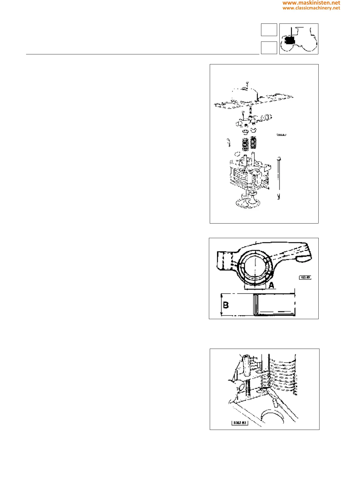
Fig. 9 - Cylinder heads, cylinders, valves and
rocker arms.
Fig. 10 - Bushing and rocker arm positions and
wear check dimensions.
A - Rocker arm bushing inside diameter
B - Rocker arm pin outside diameter
Fig. 11 - No. 5.9030.635.0 tool for tappet rod cap
removal.
engine
cylinder head
14
1
47
www.maskinisten.net
www.classicmachinery.net