Fig. 12 - Valve seat inserts and valve guides.
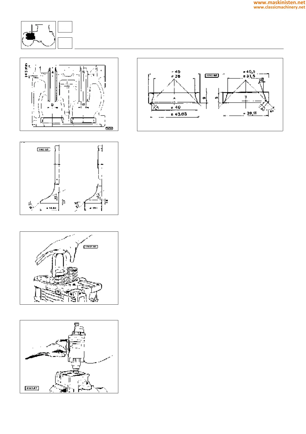
Fig. 14 - A - Intake valve
B - Exhaust valve.
Fig. 15 - Using no. 5.9030.012.0 tool to remove
valves.
Fig. 16 - Grinding valve seats.
Fig. 13 - Valve seat inserts.
Checking push rods
Examine rocker arm push rods for deformation and the rocker arm
contact ball seat for signs of seizing or roughness, if any, replace.
Make sure also the other push rod end in contact with the tappet
does not show excessive wear or nicks.
Checking valve springs
Make sure the valve springs have not lost their elasticity.
Also inspect valve springs for rust or damaged lacquering.
Checking rocker arms
Ensure the rocker arm working area is thoroughly smooth and no
nicks are shown.
Use a micrometer gauge to measure the rocker arm pin diameter;
reading should not be lower than specifications, otherwise re-
place.
Check the rocker arm bushing for excessive wear, replace as
necessary.
Check both rocker arms and valves for proper lubrication by
running the engine at idling speed, ensure the oil flow rate is
regular; should this not be the case the rocker arm bushing should
be inspected for proper installation or the ducts checked for
clogging.
Adjusting valve clearance
This adjustment is to be performed with a cold engine and piston
at T.D.C. at the end of the compression stroke (both rocker arms
shall be in uppermost position and detached from the valve
stems).
Rotate the crankshaft until the above mentioned conditions are
obtained, then use a thickness gauge to take clearance measure-
ment.
engine
cylinder head
14
1
48
www.maskinisten.net
www.classicmachinery.net