Fig. 13 - Engine governor assembly.
POINTS WHERE ADHESIVES ARE TO BE
APPLIED
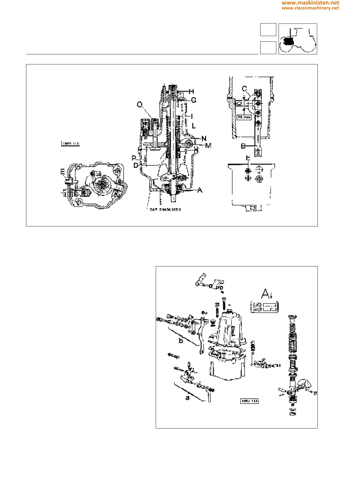
referring to fig 12
Before assembly, smear the outer surface of the
bush D, the tube E and the fitting B with Loctite
601.
Before assembly, smear the outer surface of
bush G and bush H with Loctite 601.
Before tightening nut C, smear the thread with
Loctite 270.
Before assembly, smear the thread of the lever
securing screw F with Loctite 270.
Adjusting engine speed equalizer
Fix the housing to a support.
Turn the eccentric screw E fig. 13 to obtain a
distance of 4.5+0.1 mm. between the upper
edge of the governor housing and the edge of
the sliding sleeve.
engine
SILVER 80 - 90 - 100.4 - 100.6
fuel system
Fig. 14 - Engine governor assembly components
A - Identification plate
16
1
57
www.maskinisten.net
www.classicmachinery.net