Fig. 15 - Engine-mounted governor unit.
(For engine 4-cylinders with governor mechani-
cal type).
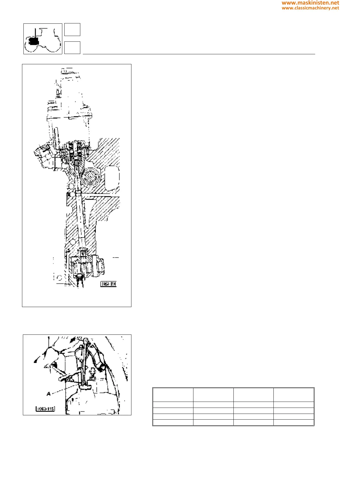
Fig. 16 - Tractor-installed engine governor unit.
Upper casing (Fig. 13)
Fit the minimum and maximum accelerator control lever travel stop
screws into the upper casing.
Mount bushing G with the relevant O-ring using nut H; install the
accelerator internal and external control levers.
Position spring-holder cap I and springs L; secure lever M and
inserted coupling N into casing.
Install travel stop rod O.
Positioning governor lever M
Operate travel stop rod O with an Allen wrench until the distance
between the lower casing edge and the travel stop rod head corner
is about 2 mm, as shown in figure 13.
Connect the upper to the lower casing, first positioning the auto-
matic extra fuel supply unit spring P on coupling N.
Calibrating engine governor
Engine governor calibration is very easy and requires no special
equipment. The procedure recommended permits all lever plays pro-
duced during engine running to be removed, since this adjustment can
be performed with engine governor assembled and engine running.
This setting is to be effected when external operations which may
involve engine governor, injection pump or injection pump control
rack replacement are performed.
Important - Whenever the governor is removed from engine, the
cable connected to the battery positive pole should be disconnec-
ted so that a sudden engine start may be prevented.
Observe the following procedure:
— start the engine and then bring to a 2000
±
100 r.p.m. by means
of the hand throttle (avoid subjecting the engine to dragging
loads and ensure it is not hunting).
— Using an Allen wrench (fig. 16) loosen the fuel maximum delivery
adjusting screw (turn it anticlockwise) until the engine is about to
stop (or keeps on running through the automatic operation of the
extra fuel supply unit stabilizing at 300 to 500 r.p.m.).
Warning: locating this condition requires most accuracy and meticulous
operating procedure and namely:
— locate approximately the point where the engine r.p.m. starts drooping;
— screw in the adjusting screw of about 3 turns to permit the
engine to be stabilized at 2000 r.p.m.;
— loosen first the adjusting screw two full turns and then continue
loosening by about 30° movements at a time and wait 2 to 3 seconds
after each screw movement until the engine stop point is located.
With the engine stopped, place the contact point of a dial gauge
on the head of screw A (fig. 16), zero the gauge, then screw in the
screw the number of turns indicated in the table, to obtain the
gauge reading indicated below:
ENGINE TYPE r.p.m. HP
No of tightening turns of
the adjusting screw
1000.4-A4 2500 80 6.3/4 (6,75 mm)
1000.4-AT2 2500 90 8.1/2 (8,5 mm)
1000.4-ATI1 2500 100 9 (9 mm)
1000.6-A1 2500 100 5.1/2 (5,5 mm)
NOTE: This adjustment can be performed at an engine oil temperture not
less than 80 °C.
Tighten the lock nut.
engine
fuel system
SILVER 80 - 90 - 100.4 - 100.6
16
1
58
www.maskinisten.net
www.classicmachinery.net