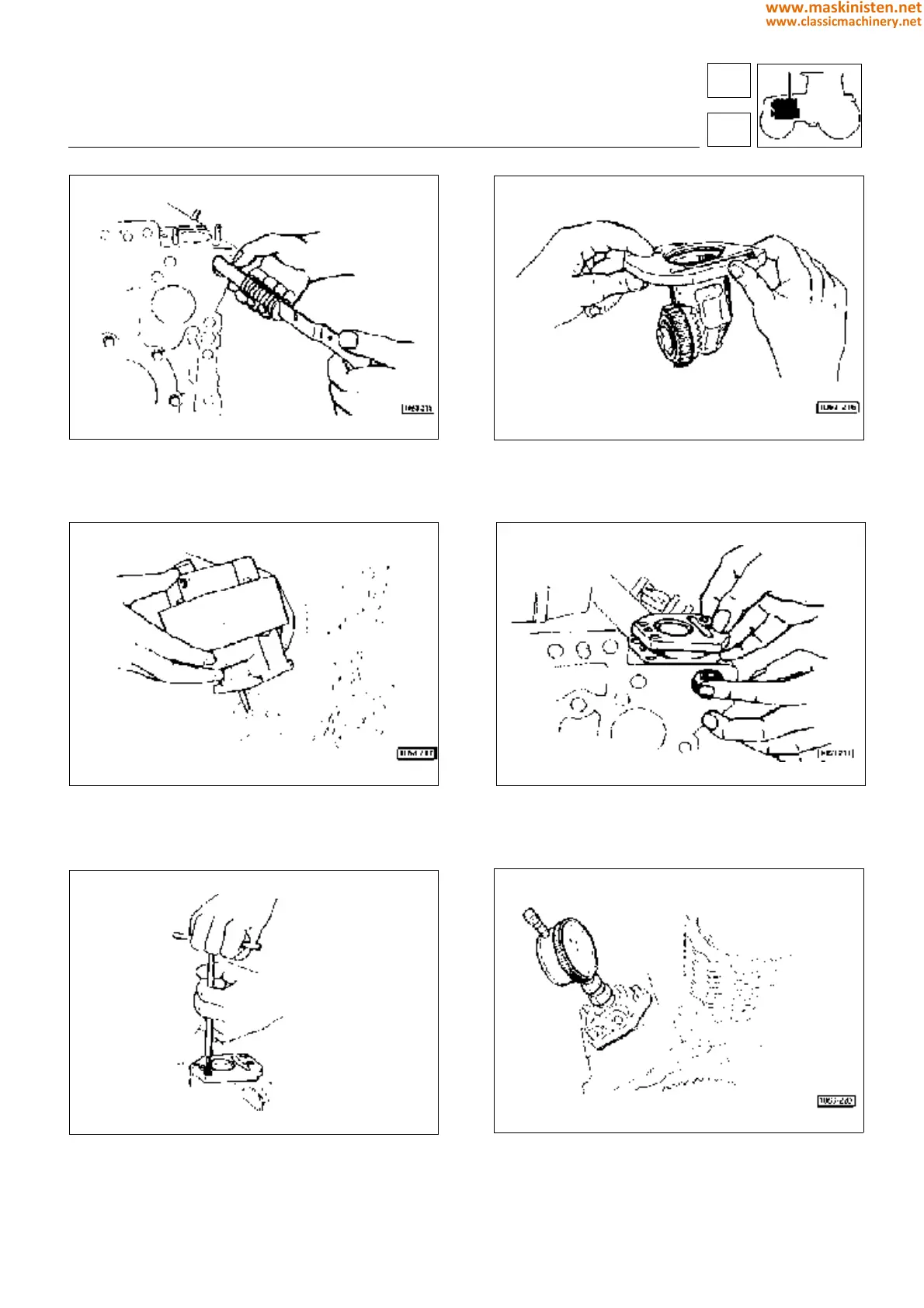
Fig. 41 - Insert the injection pump control rod in the its seat
in the cylinder block along with pressure spring and stop cap.
Make sure it is free to move inside the guide supports;
Fig. 43 - FOR TRAKTORS WITH ELECTRONIC GOVER-
NOR ONLY - After inserting a sealing ring on the stem fit the
engine actuator support in the block;
Fig. 45 - Fix the square transmission to the block tightening
the related securing screws;
Fig. 42 - ONLY FOR TRAKTORS WITH ELECTRONIC GO-
VERNOR ONLY - Assemble the square transmission control-
ling both engine governor and oil pump. As to assembly and
adjustment procedures see instructions on page 62;
Fig. 44 - FOR TRAKTORS WITH ELECTRONIC GOVERNOR
ONLY - Install the square transmission in its seat in the block
placing the special backlash adjusting shims between the gear
teeth (see instructions on page 62);
Fig. 46 - Only if necessary, determine the shim pack amounts
to be fit between injections pumps and engine block (see
instructions on page 76);
engine
assembly
1
99
www.maskinisten.net
www.classicmachinery.net