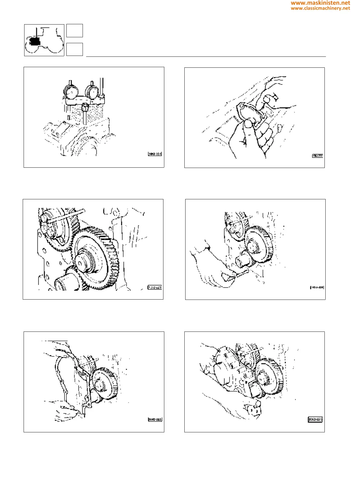
Fig. 47 - If the timing gear has been removed from the shaft
carry out valve timing for timing the engine as indicated on
page 75;
Fig. 49 - After the timing gear has been secured to shaft, fit
the idler gear taking care the chiselings on teeth be in the
same line. If one of these three gears must be replaced, valve
timing procedure shall be repeated;
Fig. 51 - Place the isogene gasket between engine block and
timing case;
Fig. 48 - After smearing the shim faces with some sealing
adhesive place the shim packs between pumps and block.
Subsequently perform injection pump installation;
Fig. 50 - Fit some locating pins or studs to centre the timing
case correctly during assembly;
Fig. 52 - The timing case should be installed paying attention
not to damage the sealing ring lip fitted inside;
engine
assembly
1
100
www.maskinisten.net
www.classicmachinery.net