Chapter 2 Installation Controls and Indicators
Branch Feeder Monitor 136_Installation Operation and Manual 19
2.4 Controls and Indicators
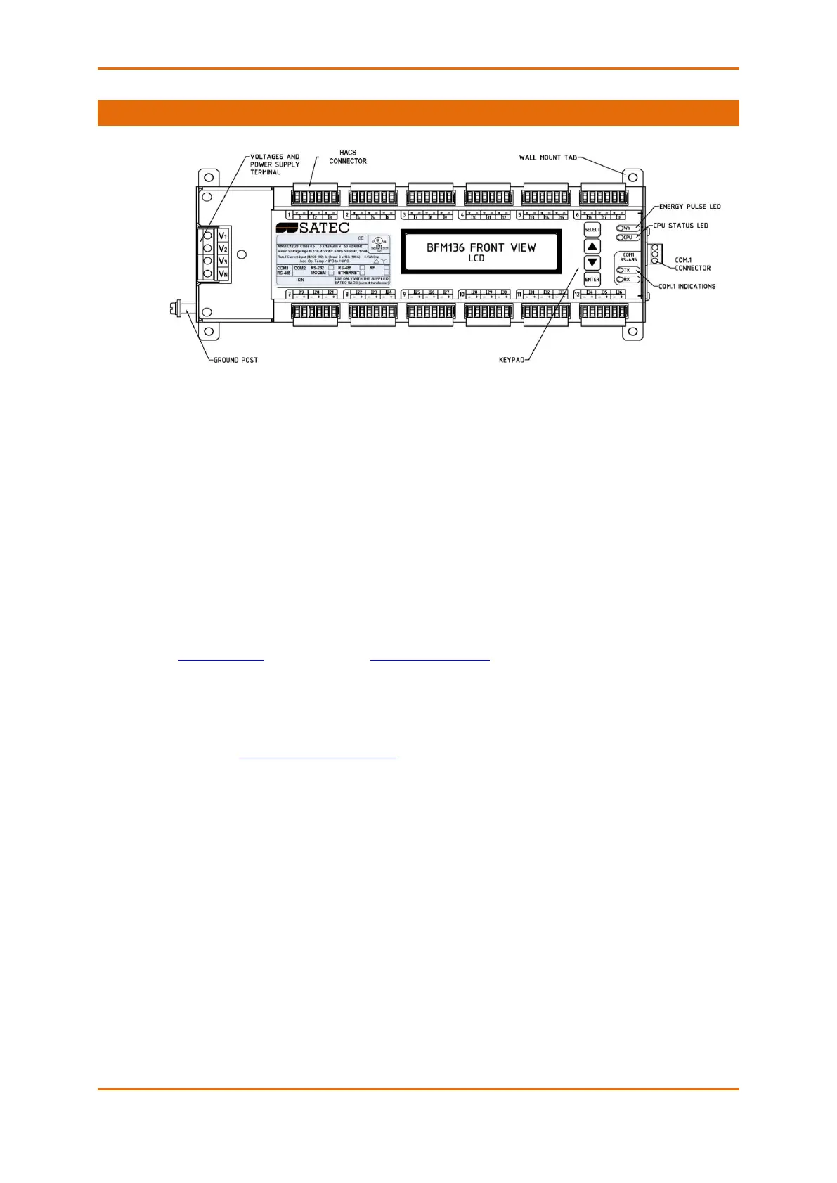
Figure 2-14 BFM136 Front View
2.4.1 Indicator LEDs
The flashing yellow CPU LED shows that the device is operational and is functioning normally.
The green TX and RX LEDs indicate activity on the COM1 communication port. The LEDs flash when the
port is receiving or transmitting data.
2.4.2 Energy Pulse LED
The red “Wh” LED flashes at a user-programmed rate when a load is applied to the device. In normal
mode, the LED pulses indicate imported Wh for a selected submeter. In energy test mode, the LED pulses
indicate either imported Wh, or imported (inductive) varh for a selected submeter. Energy test mode is
used for testing the device energy measurement accuracy. In test mode, the energy and demand
accumulators do not account for consumed energy.
See Device Options in Chapter 3 and General Meter Setup in Chapter 4 on how to put the device into
energy test mode and how to select the LED pulse rate and a submeter for testing.
2.4.3 Front Panel Display
The BFM136 is provided with an LCD display and four push buttons that are used for local meter reading
and setup. See BFM136 Display Operations in Chapter 3 for information on using the front panel display.