Chapter 2 Installation Electrical I N S T A L L A T I O N
26 PM130 PLUS Powermeter Series
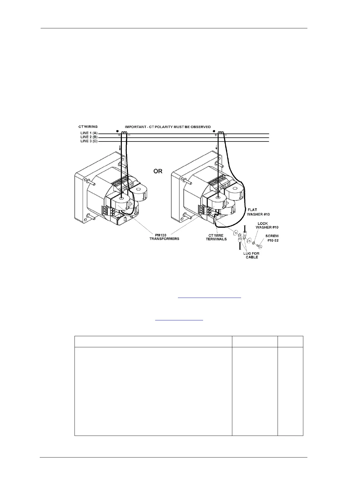
To connect to the external CT, pass the external CT wire through the
meter CT core, see Figure 2-8 for details and observe the arrow that
indicates the current direction.
In case of a retrofit application where each external CT ends with two
wires:
1. Pass one wire through the meter CT core.
2. Connect the wire to one of the meter termination screws.
3. Connect the second wire from the external CT to the termination
screw to close the loop.
Figure 2-8 Current Input Connection
Wiring Diagrams
For AC input ratings, see Technical Specifications in Appendix A for more
details.
Table 2 presents the available wiring configurations in the meter. For
more details, see Basic Meter Setup in Chapter 5.
Table 2: Wiring Configurations
3-wire 2-element Delta direct connection using 2 CTs
4-wire 3-element Wye direct connection using 3 CTs
4-wire 3-element Wye connection using 3 PTs, 3 CTs
3-wire 2-element Open Delta connection using 2 PTs, 2 CTs
4-wire 2½-element Wye connection using 2 PTs, 3 CTs
3-wire 2½-element Open Delta connection using 2 PTs, 3 CTs
4-wire 3-element Delta direct connection using 3 CTs
3-wire 2½-element Broken Delta connection using 2 PTs, 3 CTs
3-wire/4-wire connection using the current from one phase (1 CT) and
the L-L voltage from the other two phases
3-wire/4-wire connection using the current from one phase (1 CT) and
the L-L voltage from the other two phases