Chapter 2 Installation I/ O C O N N E C T I O N S
PM130 PLUS Powermeter Series 33
2.5 I/O Connections
Before I/O Module installation ensure that all incoming power
sources are shut OFF. Failure to observe this practice can
result in serious or even fatal injury and damage to
equipment.
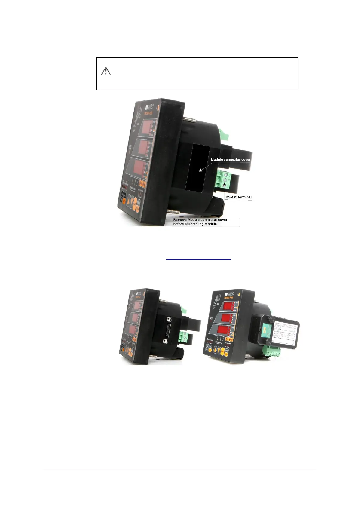
Figure 2-21 Module Connector Cover – Before Module Assembly
For I/O ratings, see Technical Specifications in Appendix A.
4DI/2DO Module
Figure 2-22 4DI/2DO Module Assembly
Relay Outputs
There are two relay outputs provided for energy pulsing, alarms, or
remote control.