Chapter 4 Using P A S S O F T W A R E Setting U P C O M M U N I C A T I O N S
64 PM130 PLUS Powermeter Series
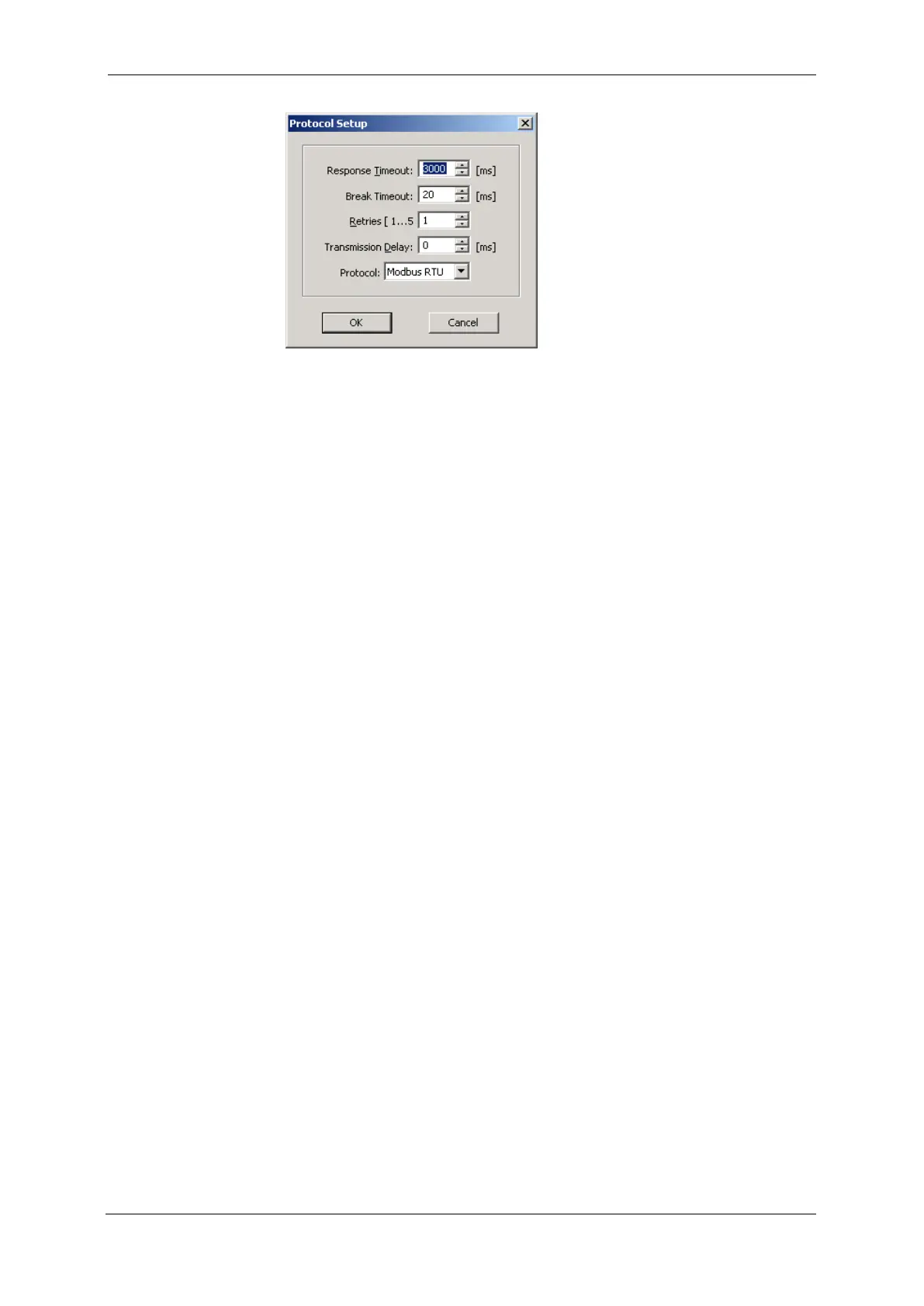
Figure 4-3: Protocol Setup Dialog Box
2. In the Protocol box, select the same communications protocol as
you have set in your meter.
3. In the Response Timeout box, define the maximum time that PAS
should wait for the meter response before announcing a failure.
4. In the Break Timeout box, define the maximum line idle time that
PAS should wait after receiving the last message character before
closing a connection with the Modbus RTU or DNP3 protocol. It does
not affect ASCII communications. Note that this time is added to the
message transfer time, and excessive increasing it may slow down
communications. If you frequently receive the “Communication error”
message, try to increase Break Timeout.
5. In the Retries box, define the number of attempts that PAS should
use to receive a response from the meter in the event the
communication fails, before announcing a communication failure.
Communicating through the Internet
If you are communicating through the Ethernet port, define the IP address
of your meter on the network.
To configure the meter IP address:
1. On the Instrument Setup tab, select Internet Site.
2. Click on the Connection tab.
3. Click on the IP address and type in the IP address of your meter.
The default IP address preset in the meter at the factory is
192.168.0.203.
4. In the Protocol box, select the communications protocol for the TCP
port. The meter provides Modbus/TCP connections on TCP port 502
and DNP3/TCP connections on port 20000. The host port is set
automatically as you select the protocol. Select Modbus RTU/TCP
for Modbus/TCP or DNP3 for DNP3/TCP.
5. In the Wait for answer box, adjust the time that PAS waits for a
connection before announcing an error.