SATEL VERSA 41
Messages with information on the currently realized operations will appear on the display.
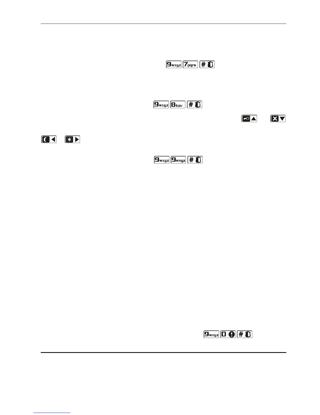
6.25.6 Checking the firmware version of control panel
Note: The function is only available in the LCD keypad.
Enter the user menu and press in turn the keys. Information on the
firmware version and build date will be displayed.
6.25.7 Checking the firmware version of modules connected to control panel
Note: The function is only available in the LCD keypad.
Enter the user menu and press in turn the keys. Name of the module with
lowest address will be shown in the upper line of the display, and information on the firmware
version and build date will appear in the lower line of the display. Using the and
keys, you can scroll through the list of modules. In the ETHM-1 module, information on the
module IP address and its MAC number will be additionally displayed after pressing the
or key.
6.25.8 Checking the current supply voltage in modules
Enter the user menu and press in turn keys. How the information is
presented depends on the type of keypad.
Note: Not all modules provide information on the current voltage.
Presentation of voltage in LCD keypad
Module name is shown in the upper line of the display, and information about voltage –
in the lower line. The list of modules can be scrolled through by using the arrow keys.
Presentation of voltage in LED keypad
Blinking of one of the LEDs designated with numbers indicates the module to which the
presented voltage level refers (the number corresponds to the module address). Use
the arrow keys to change the cursor position and move the cursor over other modules.
Voltage level is displayed on the LEDs 16-30 for modules from 1 to 15, and on the LEDs
1-15 for modules from 16 to 30. To determine the voltage, sum up the number of LEDs
which are lit (a single LED corresponds to the voltage of 1 V).
6.25.9 Outputs reset
Use the function to:
– deactivate 5. "DURESS" ALARM, 14. CHIME or 15. CONTROLLED function outputs (if the
cut-off time preprogrammed by the installer for such an output is 0, the duration of the
output activity is infinite);
– deactivate for 16 seconds the 11. FIRE DETECTORS POWER SUPPLY function output (to
clear the alarm memory of fire detectors);
– activate the 21. DETECTORS RESETTING function output.
To run the function, enter the user menu and press in turn the keys.
6.26 Service
Functions in the 0. SERVICE submenu are available after entering the service code or the
code of user who has the DOWNLOAD/SERVICE right. The functions related to control panel
programming (starting the service mode or communication between the control panel and the
DLOADX program) are described in the PROGRAMMING manual.