SECTION IV
MAINTENANCE / SERVICE
(14) Remove motor pump (6) from base weld-
ment (4).
(15) Unscrew caps (1, Figure 4-46 ) from electrical
fittings (2) on motor cover (3).
(16) Remove plastic plugs (4) and electrical fittings
(2) from motor cover (3).
(17) Remove four screws (5), lockwashers (6), motor
cover (3), and gasket (7) from manifold (8).
(18) Tag four wires (9); then remove two nuts (10),
lockwashers (11), and four wires (9) from two
terminal posts of motor (12).
(19) Cut two cable ties and remove primary
thermosat (13) and secondary thermostat (14)
from motor (12).
(20) Remove two screws (15), lockwashers (16), and
motor (12) from manifold (8).
B. Installation
(1) Install motor (12, Figure 4-46) on manifold (8)
and secure with two lockwashers (16) and
screws (15).
(2) Position secondary thermostat (14) and primary
thermostat (13) on motor (12) and secure with
two cable ties.
Page 4-43Printed in U.S.A.
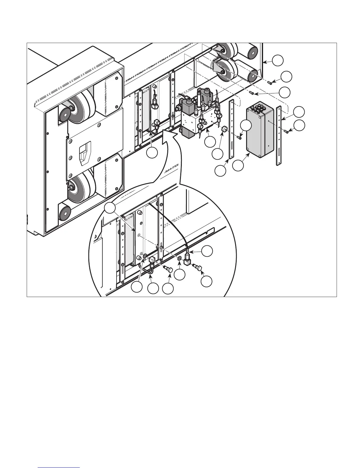
Figure 4-44. Access To Motor Pump
1
2
3
4
5
7
6
9
11
8
10
13
12
14
15
16
17
14
CA817400
© Schaerer Mayfield USA, Inc. 2004