HB-37350-810-01-50F-EN PSC1-C-10 Installation manual V2.1.docx Page 112 of 189
Version: 50F
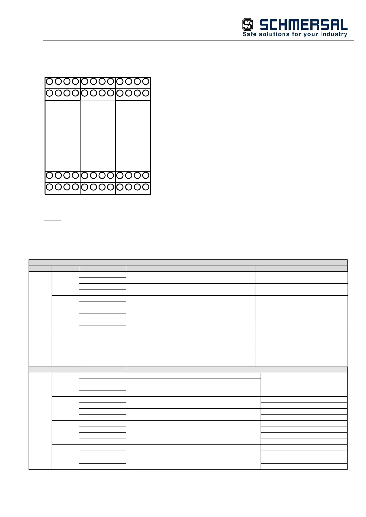
5.7.5 Terminal assignment PSC1-E-33
1
1
X09
X10
4
4
1
1
X19
X20
4
4
2.11
2.12
3.11
3.12
0.11
0.12
1.11
1.12
Q2.1
Q2.2
Q3.1
Q3.2
Q0.1
Q0.2
Q1.1
Q1.2
EXT-REL
1
1
X11
X12
4
4
1
1
X21
X22
4
4
IQ00
IQ01
Y0
Y1
IQ02
IQ03
IQ04
IQ05
IO
A1.1
A1.2
A2.1
A2.2
1
1
X13
X14
4
4
I00
I01
I02
I03
NC
NC
T0
T1
I09
I10
I11
I04
I05
I06
I07
CPU
I08
1
1
X23
X24
4
4
Note:
The read-back contacts 0.11/12, 1.11/12, 2.11/12, 3.11/12 of the internal relays Q0, Q1, Q2,
Q3 must be monitored for feedback loop monitoring (EMU) in addition to the read-back
contacts of the connected contactors or other switching amplifiers.
Safe relay output 1 (1-channel)
Safe relay output 2 (1-channel)
Safe relay output 3 (1-channel)
Safe relay output 4 (1-channel)
Device power supply +24 V DC
Attention: see: "External 24 VDC
power supply"
Device power supply +24 V DC
Device power supply 0V DC
Safe digital inputs, outputs pp switching
Safe digital inputs, outputs pp switching

 Loading...