EasyManuals Logo

schmersal PSC1-C-10 Series User Manual

schmersal PSC1-C-10 Series
189 pages
To Next Page IconTo Next Page
To Previous Page IconTo Previous Page
Page #114 background imageLoading...
Page #114 background image
Installation manual
HB-37350-810-01-50F-EN PSC1-C-10 Installation manual V2.1.docx Page 114 of 189
Version: 50F
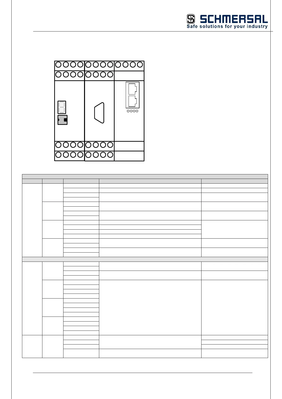
5.7.6 Terminal assignment PSC1-E-37 in preparation
X1
UE1+
UE1-
1
1
X11
X12
4
4
1
1
X21
X22
4
4
1
1
X13
X14
4
4
I00
I01
I02
I03
T0
T1
I09
I10
I11
I04
I05
I06
I07
CPU
I08
1
1
X23
X24
4
4
I12
I13
Y0
Y1
Q4.1
Q4.2
Q5.1
Q5.2
Q0
Q1
Q2
Q3
REL
A1.1
A1.2
A2.1
A2.2
1 4
FE
FB 1.1
FB 1.2
1 4
X99
Terminal assignment
Unit
Terminal
Pin
Description
Note
REL
X11
1 A1.1
Device power supply +24 VDC
2 A1.2
Device power supply +24 VDC outputs
3 A2.1
Device power supply 0 VDC
4 A2.2
X12
1 I 12
Safe digital inputs
2 I 13
3 Y0
Signal outputs
4 Y1
X21
1 Q0
Output pn switching Q0_PP / pp switching Q0
optionally can be configured in the
parameters via SafePLC2
2 Q1
Output pn switching Q1_PN / pp switching Q1
3 Q2
Output pn switching Q2_PP / pp switching Q2
4 Q2
Output pn switching Q3_PN / pp switching Q3
X22
1 Q4.1
Safe relay output
2 Q4.2
3 Q5.1
Safe relay output
4 Q5.2
CPU
X13
1 NC
No function
2 NC
3 T0
Pulse outputs
4 T1
X14
1 I 00
Safe digital inputs
2 I 01
3 I 02
4 I 03
X23
1 I 04
2 I 05
3 I 06
4 I 07
X24
1 I 08
2 I 09
3 I 10
4 I 11
X99
1 NC
No function
2 NC
3 NC
4 FE
Functional earth
Connect to FE or PE of the control
cabinet (use short cables)

Table of Contents

Questions and Answers:

Question and Answer IconNeed help?

Do you have a question about the schmersal PSC1-C-10 Series and is the answer not in the manual?

schmersal PSC1-C-10 Series Specifications

General IconGeneral
Brandschmersal
ModelPSC1-C-10 Series
CategoryControl Unit
LanguageEnglish

Related product manuals