4 Maintenance
4--11
F--9999--8 Build 8 Issue 1
4.1.5 Timing Procedures
Before machine timing can be performed a mechanic must remove the timing chain (Fig. 4-11. ) from the
Main Drive sprocket, Plastic Feed/ Tip Die sprocket, and Pile Feeder Drive sprocket. This is accomplished
by loosening the Chain Take--up and removing the chain.
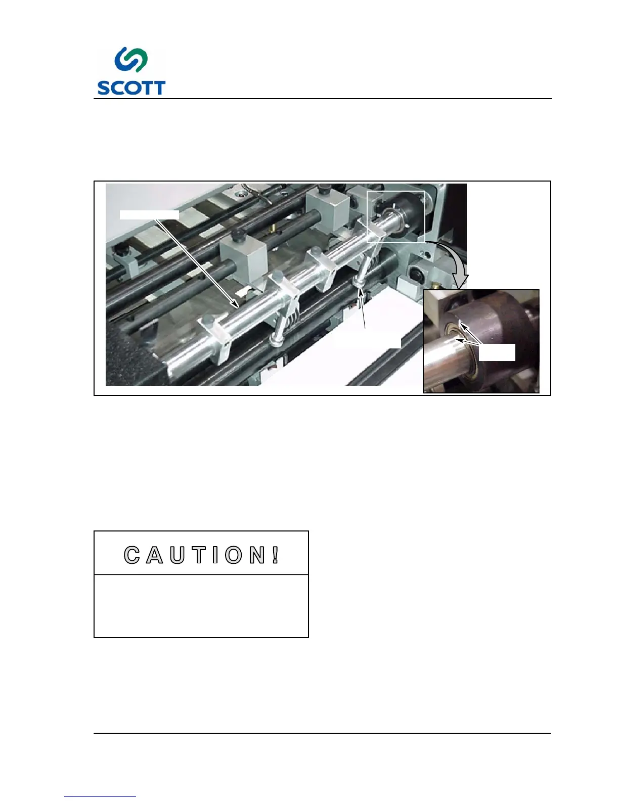
VACUUM BAR
PAPER VACUUM
NOZZLE
TIMING
MARK
Fig. 4-12. Position the Paper Vacuum Nozzle
4.1.5.1 Feeder Timing
Step: 1. Locate vacuum bar on feeder section.
Step: 2. Nozzles on vacuum bar are correctly timed when positioned as shown in Fig. 4-12.
Step: 3. If nozzles are incorrectly aligned, perform Steps 4 and 5.
Step: 4. Turn feeder drive shaft sprocket counterclockwise to move nozzles through normal rotation
cycle.(See Fig. 4-11. )
Step: 5. When nozzles have reached correct position, vacuum bar will be properly timed. (See Fig. 4-12. ).
Incorrect rotation (clockwise) of feeder
drive sprocket will set vacuum bar out of
proper timing sequence with machine. If
this occurs, perform the following:
● Cycle paper pile feeder through two complete rotation (See Fig. 4-12. )
● Turn feeder drive shaft counterclockwise to relocate nozzles in correct position. (See Fig. 4-12. )
● Rotation of vacuum bar to position nozzles will not set feeder assembly in proper timed position.