4 Maintenance
4--40
F--9999--8 Build 8 Issue 1
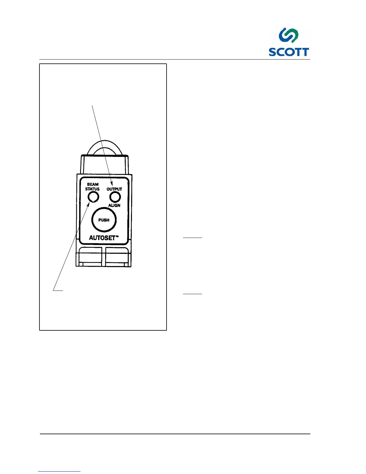
Dual Function LED Indicator
Triple Function LED Indicator
- GREEN indicates “ON” after AutoSet routine
- Flashes AMBER after excess gain
(sensitivity) adjustment
-- RED indicates output status illuminates when
transistors are in the “ON” state condition
-- GREEN indicates flash rate alignment
-- AMBER flashes when AutoSet routine is complete
Fig. 4-45. Fiber O ptic Amplifier Adjustment
To AutoSet Fiber Optic Amplifiers:
Step: 1. E--Stop the machine.
Step: 2. Place sensor into light state condition.
Step: 3. Press and hold “AutoSet” button until
Alignment Indicator (Green LED) begins
to flash.
Step: 4. Release button beam status indicator
(Green LED) will illuminate.
Step: 5. Alignment indicator flashes Amber when
AutoSet routine is complete.
Test the amplifier setting:
Step: 6. Use a piece of 20# bond (copy paper)
and put it between the tips of the optic. A
red light should turn on indicating that the
amplifier is now set.
To Adjust excess gain (sensitivity) of Fiber Optic
Amplifier:
Note ! This optional adjustment is to be
initiated after performing the AutoSet
routine
Step: 1. Tap “AutoSet” button twice. When Status
Indicator (Amber LED) flashes, excess
gain (sensitivity) has been increased.
Note ! Procedure can be repeated until Max
Excess Gain is achieved (Amber LED
will cease to flash at Max Excess
Gain)