1.2
SEL-734B Capacitor Bank Control Field Reference Guide Date Code 20170207
Overview
SEL-734B Front Panel
SEL-734B Front Panel
This section describes the general front-panel functionality of the SEL-734B.
Refer to the associated Capacitor Bank Control Design Template Guide for
information on the front-panel functionality when the device is factory-
programmed for capacitor bank control.
The function of front-panel LEDs and pushbuttons are factory-programmed
based on your enclosure model option. Blank labels shipped with the device
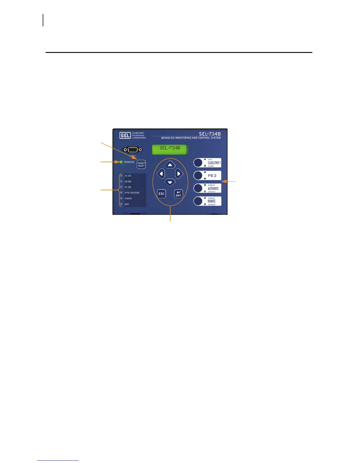
can be used to indicate new functionality. Figure 1.2 depicts the front panel of
the SEL-734B with default labels installed as on the standalone device.
Figure 1.2 SEL-734B Front Panel
ENABLED LED
This LED shows the diagnostics status of the SEL-734B. An illuminated
ENABLED LED indicates that the SEL-734B is operating properly. If the
ENABLED LED turns off, the SEL-734B requires service.
Configurable LEDs
and Pushbuttons
All front-panel LEDs except for the ENABLED LED are configurable. The
SEL-734B has four control pushbuttons and one TARGET RESET button. Custom
labels on the front panel and settings in the device define the functionality of
the pushbuttons and LEDs. Refer to the appropriate design template guide for
details on the functionality of the capacitor bank control program.
Test Front-Panel LEDs
Press the TARGET RESET button to illuminate all front-panel LEDs for test. This
pushbutton is configurable and performs other functions for capacitor bank
control. Please refer to the appropriate design template guide for details on the
programmed functionality of the TARGET RESET pushbutton.
Menu Pushbuttons
The menu pushbuttons provide access to the front-panel menu and are not
configurable. You can use the menu to perform the following tasks:
➤ View the status and diagnostics of the SEL-734B
➤ View metering data
➤ View and change device settings
➤ View event data
ENABLED LED
TARGET RESET
Button
Menu Pushbuttons
Six Configurable
LEDs
Four Pushbuttons
and Eight Configurable LEDs
 Loading...