C.5
Date Code 20170207 Field Reference Guide SEL-734B Capacitor Bank Control
Installation Examples
Full-Size Enclosures With Individual Sensor Connectors
Figure C.4 Full-Size Enclosure With Individual Sensor Connectors (Installed With a Single Sensor and Generic
Neutral Current Sensor)
Full-Size Enclosures With Individual Sensor
Connectors
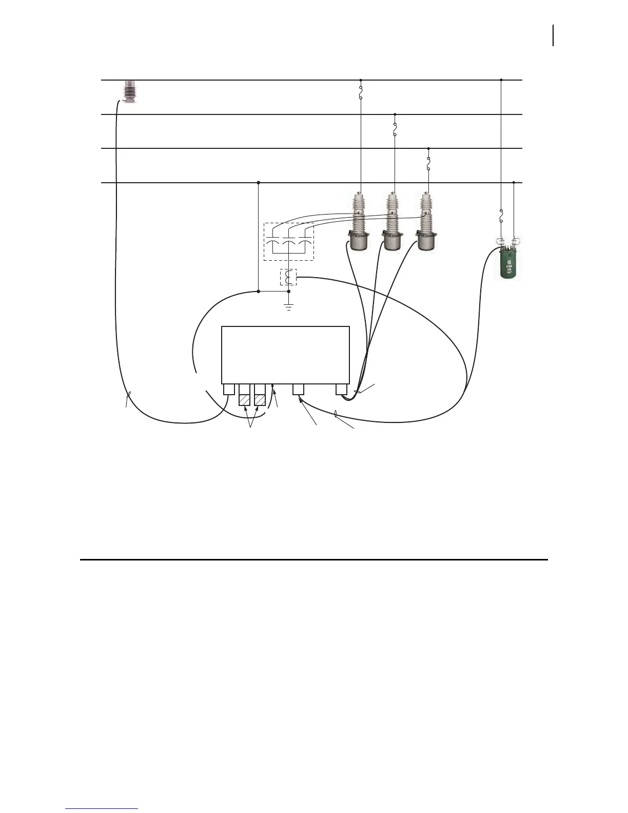
Figure C.5 shows a diagram of a typical installation of the Full-Size Enclosure
model with individual sensor connectors.
Ground Conductor
Ground the SEL-734B Capacitor Bank Control cabinet by using the ground
lug before making any other connections to the cabinet.
Sensor Cables
One measurement cable connects to one combination sensor. For three-phase
sensing, connect all three sensors to the enclosure (see Figure C.5 and
Figure C.3). If sensing only a single phase, install SEL-C530S shorting plugs
into the unused connectors to short them to neutral and minimize noise (see
Figure C.4).
Control
Power
Transformer
A-Phase
B-Phase
C-Phase
Neutral
Three
Single-Phase
Switches
Capacitor
Bank
Combo
Sensor
Neutral
Current
Sensor
SEL-734B Enclosure,
Individual Sensor Connectors
Sensor
Connectors
Shorting Plugs
(SEL-C530S)
Individual
Sensor Cable
(SEL-C530, Lindsey 9-587/XX/9-582)
Control
Connector
Power Supply/
Neutral Sensor
Connector
Power Supply/Neutral Sensor Cable (SEL-C532)
Control Cable
(SEL-C531, SEL-C537,
SEL-C538)
Cabinet
Ground Lug