1.4
SEL-734B Capacitor Bank Control Field Reference Guide Date Code 20170207
Overview
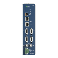
Enclosure Front
Main CPU Board
Slot B contains the main CPU board. This slot also contains two EIA-232
communications ports. The optional Ethernet port is also located on this
board.
Optional
Communications
Board
Slot C may contain an optional communications or analog input board.
Typically, this slot is empty.
Input/Output Board
Slot D contains an input/output (I/O) board. The board contains the output
contacts to operate the capacitor bank switches. All output contacts on this
board operate the capacitor bank switches.
Voltage and Current
Measurement Board
Slot E contains the low-energy analog (LEA) input board. Three voltage
sensors and three current sensors connect to this board. Optionally, the board
can have a fourth neutral current channel.
Note: There are two versions of the LEA cards for the SEL-734B for use
depending on the application.
➤ 4 LEA Current Sense Inputs and 3 LEA Voltage Sense
Inputs (1 M input impedance, 0.1–12.5 Vac and 10 M
input impedance, 0.4–25.0 Vac, respectively). This card is
used in Full-Size Enclosures in which sensing and control of
the three phases are typically independent, and combination
line post sensors are used (which provide both voltage and
current signals for each phase).
➤ 4 LEA Current Sense Inputs and 3 Single-Phase Voltage
Sense Inputs (1 M input impedance, 0.1–12.5 Vac and
10 M input impedance, 57–150 Vac, respectively). This
card is used in compact enclosures in which there is typically
only one phase of sensing and the three capacitor switches are
operated simultaneously. In these applications, a single
current-only line post sensor is used, and the control power
transformer voltage is used as the voltage sensing input.
Integrated 15 Vdc
Power Supply Board
Slot Z optionally contains the integrated 15 Vdc power supply for accessories.
This module provides a 15 Vdc source to power accessories in the cabinet.
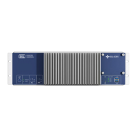
Enclosure Front
The following section provides a description of the front of the enclosure.
Front-Panel Voltage
Jacks
The voltage test jacks labeled LINE and NEUTRAL are for use with a handheld
voltage meter to measure the voltage provided to the cabinet. These jacks are
not designed to be used as external power jacks.
Fuse Holders
The device is electrically protected by a 12 A fuse labeled LINE on the front
panel. The fuse labeled Neutral MOV protects the neutral leg of the MOV surge
arrestor. This fuse will not disconnect the neutral from the cabinet; it only
disconnects the neutral of the MOV to protect against damage in the unlikely
event of an MOV failure.