C.7
Date Code 20170207 Field Reference Guide SEL-734B Capacitor Bank Control
Installation Examples
Compact 7-Pin Connectorized Enclosures
Compact 7-Pin Connectorized Enclosures
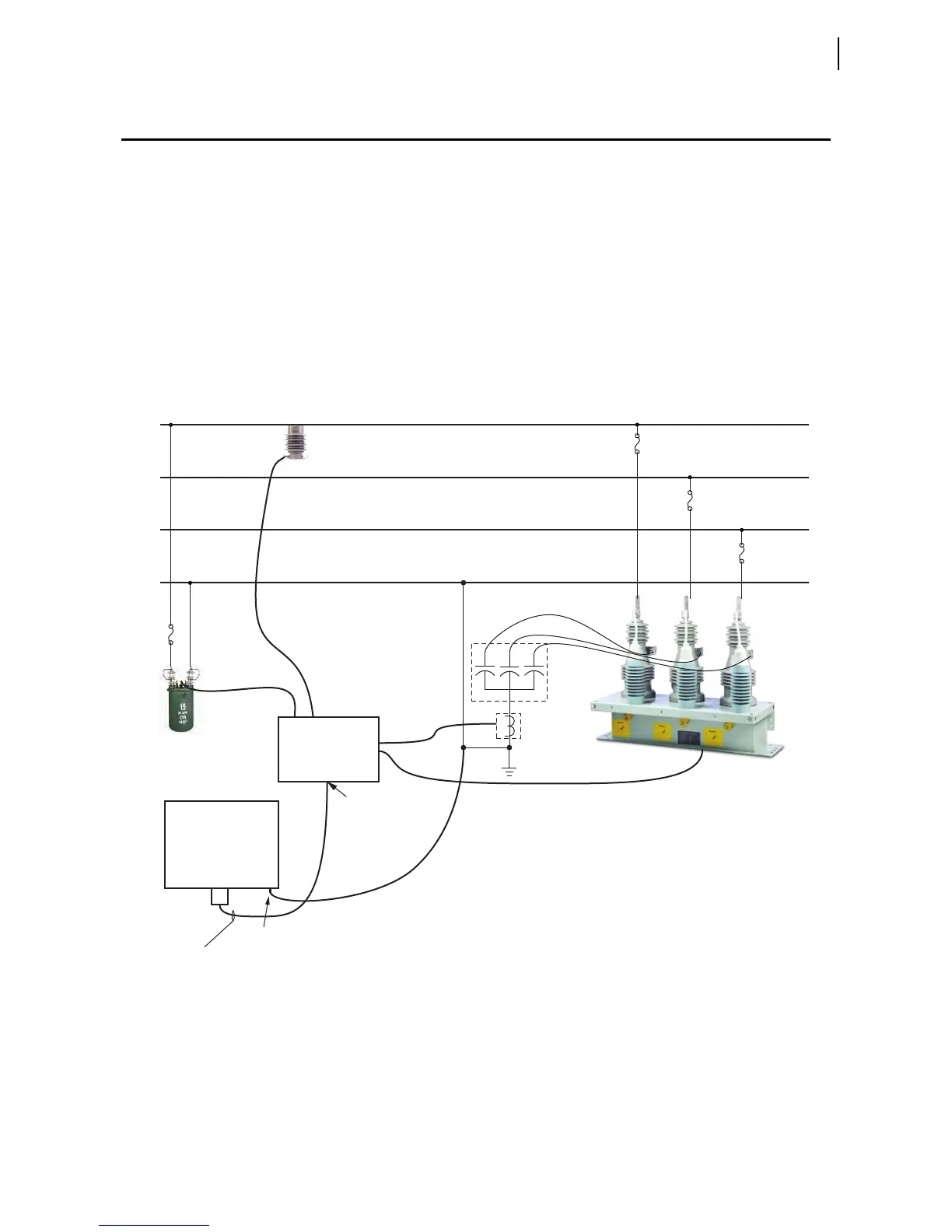
Figure C.6 shows a diagram of a typical installation of the Compact 7-Pin
Enclosure. Ground the SEL-734B Capacitor Bank Control cabinet chassis
before making any other connections to the cabinet.
The SEL-C548 cable connects to a 120 Vac control power transformer, a
three-phase capacitor bank switch, one current sensor, and one neutral current
sensor. A 7-pin circular connector mates with the enclosure, and a weather-
tight seal mounts to a penetration on the junction box.
The SEL-734B measures the output voltage of the control power transfer and
uses the signal for capacitor bank control. The current sensor should be
installed on the same phase on which the control power transformer is
installed.
Figure C.6 Compact 7-Pin Enclosure
Neutral
Capacitor
Bank
Neutral
Current
Sensor
SEL-734B Compact
7-Pin Enclosure
A-Phase
B-Phase
C-Phase
Current
Sensor
Junction Box
7-pin
Control and
Sensor Cable
(SEL-C548)
Weathertight
Seal
Control
Power
Transformer
Three-Phase
Capacitor Bank
Switch
Cabinet
Ground Lug



 To Next Page