2.4
SEL-734B Capacitor Bank Control Field Reference Guide Date Code 20170207
Field Connections to the Enclosures
Connections to Full-Size Enclosures
Sensor Cables for Enclosures With the Combined Sensor Connector
Each of the following cables connects to the 14-pin measurement connector.
Use Table 2.4 to identify the sensor cable that is compatible with your
installation.
Individual Sensor
Connector Versions
Figure 2.2 shows the bottom view of the enclosure with individual sensor
connectors. This version contains five connectors located on the bottom.
J A-Phase Current Sensor, Positive Polarity
K Reserved
L B-Phase Current Sensor, Positive Polarity
M Current Sensors Common
N C-Phase Current Sensor, Positive Polarity
P Reserved
Table 2.3 Pinout of Combined Sensor Connector for Full-Size
Enclosures (Sheet 2 of 2)
Pin Number Description
Table 2.4 Sensor Cables for Full-Size Enclosures With the Combined Sensor Connector
Cable Cable Diagram Notes
R-22748/XX,YY Visit selinc.com/products/73x/734b-full-enclosure/ ➤ Connects to three Lindsey Manufacturing
sensors and one Lindsey Neutral Current
Sensor
➤ 4-Pin (14S-2P) male connectors
➤ Installation example: Figure C.1
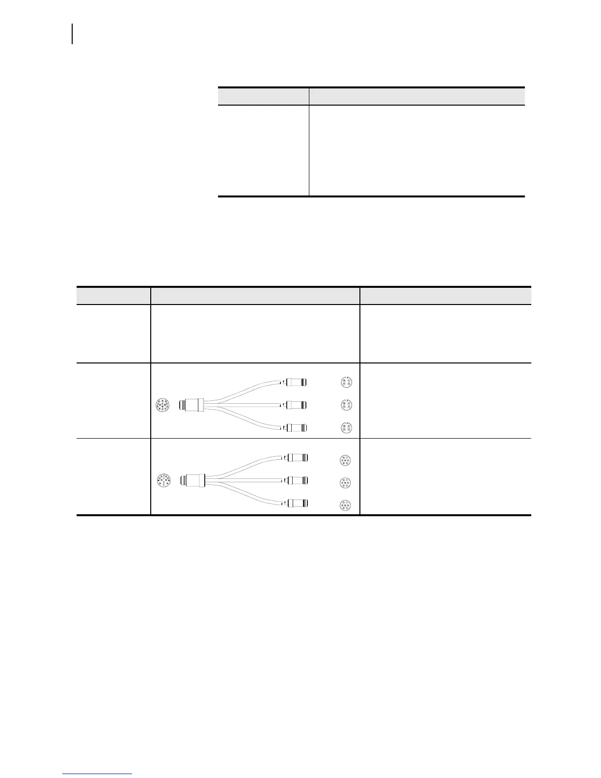
SEL-C529
➤ Connects to three Lindsey Manufacturing
sensors
➤ Three 4-pin (14S-2P) male connectors
➤ Compatible with security sleeve 9250011
➤ Installation example: Figure C.2
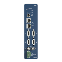
SEL-C536
➤ Connects to three Piedmont LSCV-SEL
sensors
➤ Three 7-pin (16S-1P) male connectors
➤ Compatible with security sleeve 9250011
➤ Installation example: Figure C.2
J1
Phase 1
Phase 2
Phase 3
J2
J3
J4
J1
Phase 1
Phase 2
Phase 3
J2
J3
J4