2.8
SEL-734B Capacitor Bank Control Field Reference Guide Date Code 20170207
Field Connections to the Enclosures
Connections to Compact Enclosures
Socket-Based
Versions
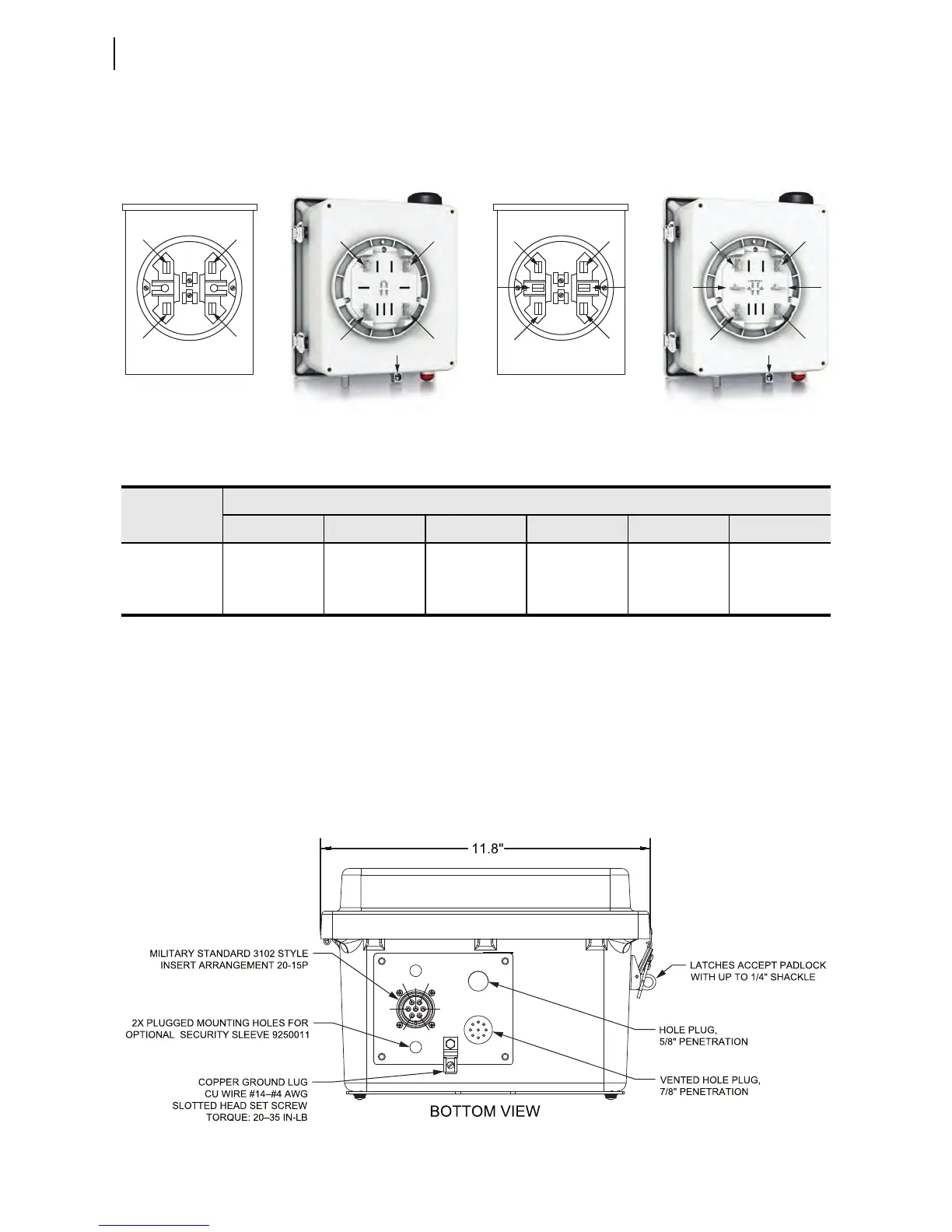
Figure 2.3 shows the back of the socket-based enclosures, and Table 2.11
shows the pinout of the socket stabs. SEL does not offer cables to install the
socket-based enclosures. The socket-base should be wired to the field devices
in accordance with Table 2.11.
Figure 2.3 4- and 6-Jaw Socket Stabs
7-Pin Connectorized
Versions
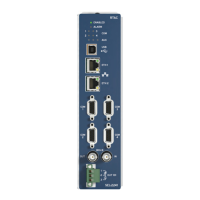
The Connectorized version of the Compact Enclosure connects to equipment
in the field through one 7-pin connector located on the bottom of the
enclosure.
Figure 2.4 Bottom View of Connectorized Compact Enclosure
Table 2.11 Socket Stab Configurations
a
a
Where:
+CPT: 120 Vac Control Power Transformer, Positive Polarity
–CPT: 120 Vac Control Power Transformer, Neutral
OPEN: Open Operating Signal Output Contact
CLOSE: Close Operating Signal Output Contact
•IA: Phase Current Sensor Input, Positive Polarity
IA: Phase Current Sensor, Common
•IN: Neutral Current Sensor Input, Positive Polarity
NOTE: The ground lug is isolated from the control power transformer neutral.
Enclosure
Socket Option
Socket Stab Number and Function
1 2 3 4 5 6
4-Jaw +CPT –CPT OPEN CLOSE — —
6-Jaw Option A +CPT –CPT •IN •IA OPEN CLOSE
6-Jaw Option B IA –CPT +CPT OPEN •IA CLOSE
2
1
4
3
4-Jaw Socket-Based Version
2
1
6
43
5
6-Jaw Socket-Based Version
2
1
43
4-Jaw Meter Socket 6-Jaw Meter Socket
21
6
43
5
Ground Lug Ground Lug
D
E
FA
B
C
G