2.7
Date Code 20170207 Field Reference Guide SEL-734B Capacitor Bank Control
Field Connections to the Enclosures
Connections to Compact Enclosures
Cables for Enclosures With Individual Sensor Connectors
The following sensor cables connect to an individual phase sensor connector.
Please use Table 2.10 to identify the cable that is compatible with your
installation.
Connections to Compact Enclosures
This section describes the field connections for Compact Enclosure versions.
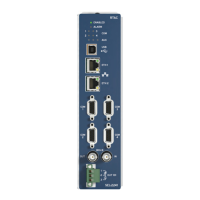
Table 2.9 Control Cables for Full-Size Enclosures With Individual Sensor Connectors
SEL Cable Cable Diagram Notes
SEL-C537 ➤ Connects to three switches
➤ 5-pin female connector
➤ Military standard 3106 Style
➤ Insert arrangement 18-11S
➤ Installation example: Figure C.5
➤ Control power transformer connected sepa-
rately
SEL-C538
➤ Connects to three switches
➤ 6-pin female connector
➤ Military standard 3106 Style
➤ Insert arrangement 18-12S
➤ Installation example: Figure C.5
➤ Control power transformer connected sepa-
rately
J1
Phase 1
Phase 2
Phase 3
J2
J3
J4
J1
Phase 1
Phase 2
Phase 3
J2
J3
J4
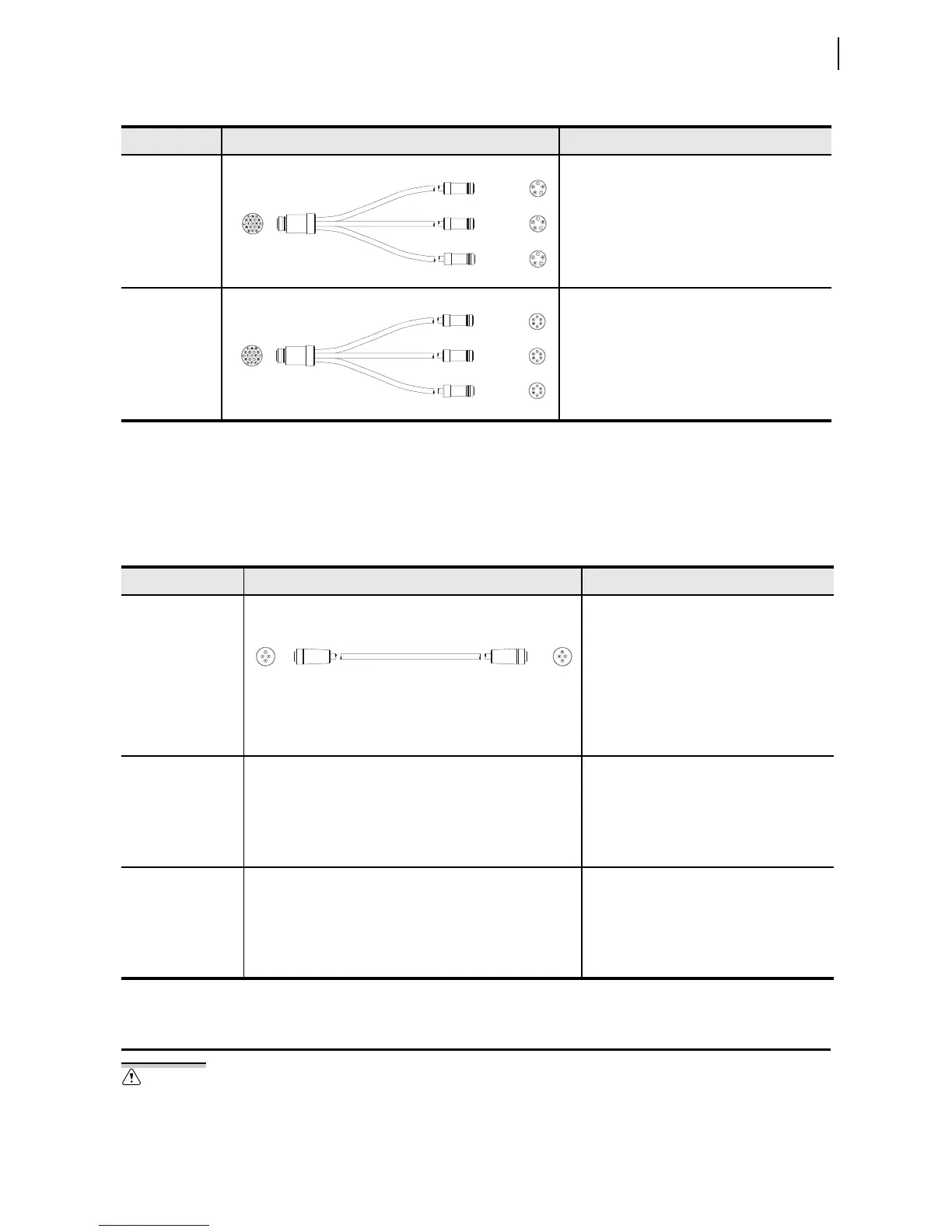
Table 2.10 Sensor Cables for Full-Size Enclosures With Individual Sensor Connectors
Cable Cable Diagram Notes
SEL-C530 ➤ Connects to one Lindsey Manufacturing
sensor
➤ 4-pin male connector, Ecomate C016
20H003 100 12
➤ Alternative to the Lindsey
9-587/XX/9-582 cable
➤ Installation example: Figure C.3
➤ Compatible with security sleeves
915900304 and 915900224
Lindsey
9-587/XX/9-582
Visit selinc.com/products/73x/734b-full-enclosure/
➤ Connects to one Lindsey Manufacturing
sensor
➤ 4-pin male connector, Ecomate C016
20H003 100 12
➤ Alternative to the SEL-C530 cable
➤ Installation example: Figure C.3
SEL-C530S Contact your SEL representative for the cable diagram
➤ Sensor connector shorting plug
➤ Install into unused sensor connectors to
prevent noise measurement
➤ Installation example: Figure C.4
➤ Compatible with security sleeves
915900304 and 915900224
Ground the SEL-734B Capacitor Bank
Control cabinet before making any
other connections to the cabinet.
 Loading...