2.6
SEL-734B Capacitor Bank Control Field Reference Guide Date Code 20170207
Field Connections to the Enclosures
Connections to Full-Size Enclosures
Power Supply/Neutral Sensor Connector J2
Connector J2 connects to the 120 Vac control power transformer and a neutral
current sensor. Table 2.7 lists the functions of the connector’s pins.
Control Cables for Enclosures With Individual Sensor Connectors
Each of the following cables connect to the 19-pin control connector. Use
Table 2.9 to identify the control cable that is compatible with your installation.
L Reserved
M A-Phase 52a Auxiliary Contact
N A-Phase 52b Auxiliary Contact
P B-Phase 52a Auxiliary Contact
R B-Phase 52b Auxiliary Contact
S C-Phase 52a Auxiliary Contact
T C-Phase 52b Auxiliary Contact
U System Neutral
V System Neutral
Table 2.6 Pinout of Control Connector J1 for Full-Size Enclosures With
Individual Sensor Connectors (Sheet 2 of 2)
Pin Number Description
Table 2.7 Pinout of Power Supply/Neutral Connector J2 for Full-Size
Enclosures With Individual Sensor Connectors
Pin Number Description
A 120 Vac Control Power Transformer
B Control Power Transformer Neutral
C Neutral Sensor, Positive Polarity
D Neutral Sensor, Common
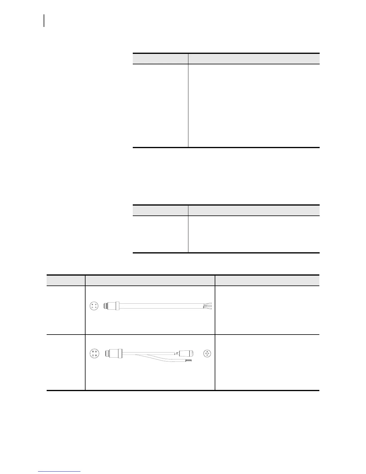
Table 2.8 Power Supply/Neutral Sensor Control Cables for Full-Size Enclosures With Individual Sensor
Connectors
Cable Cable Diagram Notes
SEL-C532 ➤ Connects to the control power transformer
and a neutral sensor
➤ Wire pigtails for neutral sensor and control
power transformer
➤ Installation example: Figure C.5
➤ Compatible with security sleeves 915900304
and 915900224
SEL-C539
➤ Connects to the cable of one Lindsey Manu-
facturing R-2298155 neutral sensor and the
control power transformer
➤ 4-pin male connector
➤ Ecomate
®
C016 20H003 100 12, mates with
Lindsey Sensor R-22981SS
➤ Installation example: Figure C.3
➤ Compatible with security sleeve 915900304
J1
J1
Power Supply
J2
 Loading...