1.3
Date Code 20170207 Field Reference Guide SEL-734B Capacitor Bank Control
Overview
SEL-734B Rear Panel
SEL-734B Rear Panel
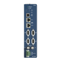
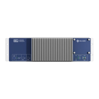
Figure 1.3 shows a diagram of the rear-panel connections on a typical
SEL-734B model.
Figure 1.3 Top Label and Rear Panel
A label on the top of the SEL-734B defines the function of each rear-panel
terminal or communications port.
The rear panels are divided into six slots: Slot A, B, C, D, E, and Z. Terminals
are designated by the slot letter and the terminal number. For example, Slot D
terminals are designated D01 through D14.
Power Supply Board
Slot A contains the circuit board to power the SEL-734B. This slot also
contains two Form A output contacts, one Form C output contact, and two
digital inputs. In the Full-Size Enclosure option, the two Form A contacts
operate the capacitor bank switch.



 To Next Page