2.5
Date Code 20170207 Field Reference Guide SEL-734B Capacitor Bank Control
Field Connections to the Enclosures
Connections to Full-Size Enclosures
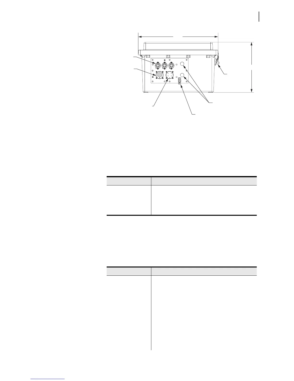
Figure 2.2 Bottom View of Enclosure With Individual Sensor Connectors
Sensor Connectors J3, J4, and J5
Connector J3, J4, and J5 each connect to a single combination (measures
voltage and current) sensor. Install the SEL-C530S shorting plug in unused
connectors to minimize noise measurement. Table 2.5 lists the functions of
each pin.
Control Connector J1
Connector J1 sends open and close signals to each capacitor bank switch and
includes provisions to monitor the auxiliary (52a and 52b) contacts. Table 2.6
lists the functions of the connector’s pins.
19-Pin Control
Connector J1
Style 3102
Insert Arrangement
22-19P
4-Pin Connectors
J3, J4, J5
4-Pin Connector J2
Style 3102
Insert Arrangement
22-14P
Ground Lug
0.62” (2 PLCS)
10.02”
16.00”
Lockable
Latches, 0.38”
(2 Places)
Table 2.5 Pinout of Individual Sensor Connectors J3, J4, and J5
Pin Number Description
1 A-, B-, or C-Phase Current Sensor
2 Current Sensor Common
3 A-, B-, or C-Phase Voltage Sensor
4 Voltage Sensor Common
Table 2.6 Pinout of Control Connector J1 for Full-Size Enclosures With
Individual Sensor Connectors (Sheet 1 of 2)
Pin Number Description
A Not Connected
B System Neutral
C Open A-Phase
D Close A-Phase
E Reserved
F Open B-Phase
G Close B-Phase
H Reserved
J Open C-Phase
K Close C-Phase