Date Code 20170207 Field Reference Guide SEL-734B Capacitor Bank Control
Section 2
Field Connections to the Enclosures
Overview
This section describes the field connections to the enclosure. A description of
the control and sensor cables is also given. Detailed drawings of the various
cables are provided in Appendix D: Cable Drawings.
Connections to Full-Size Enclosures
SEL offers two versions of the Full-Size Enclosure. The Combined Sensor
Connector version contains one 14-pin sensor connector and one 19-pin
control connector. The Individual Sensor Connector version contains three
4-pin sensor connectors, one 19-pin control connector, and one 4-pin power
supply/neutral sensor connector.
Combined Sensor
Connector Version
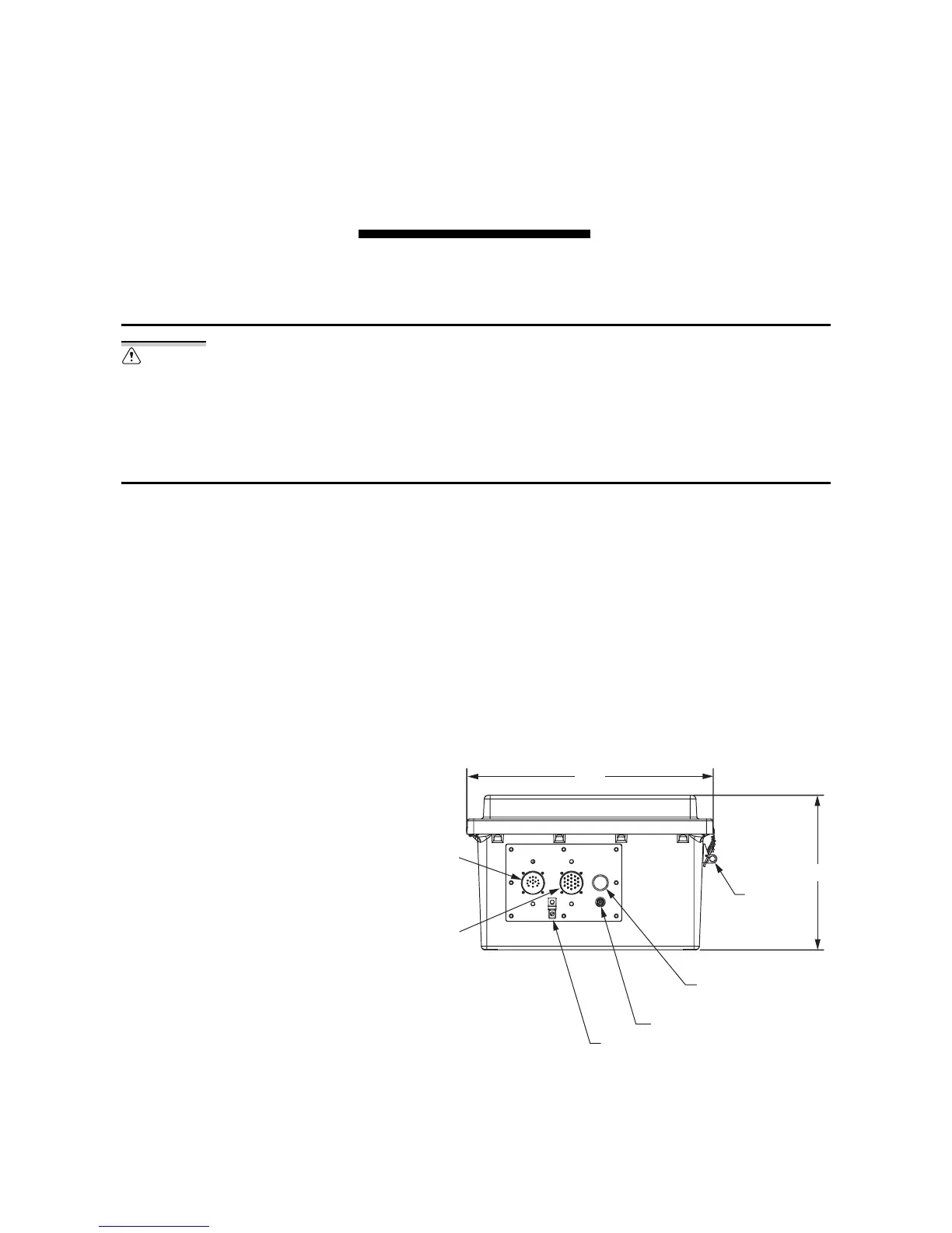
Figure 2.1 shows the bottom view of the Full-Size Enclosure model with the
combined sensor connector. All three phase sensors and the neutral sensor
connect to the 14-pin connector on the bottom of the enclosure. Optionally,
you can connect a neutral current sensor to terminal blocks inside the
enclosure and route the cabling through openings on the bottom of the
enclosure. The 19-pin connector routes the control power to the switches from
the enclosure.
Figure 2.1 Bottom View of Enclosure With Combined Sensor Connector
Ground the SEL-734B Capacitor Bank
Control cabinet before making any
other connections to the cabinet.
14-Pin Sensor
Connector J1
Style 3102
Insert Arrangement
22-19P
19-Pin Control Connector J2
Style 3102
Insert Arrangement
22-14P
Ground Lug
Clock Antenna
Surge Arrestor Type TNC
0.88” Diameter
Penetration
10.02”
16.00”
Lockable
Latches, 0.38”
(2 Places)