2.2
SEL-734B Capacitor Bank Control Field Reference Guide Date Code 20170207
Field Connections to the Enclosures
Connections to Full-Size Enclosures
19-Pin Control Connector
The control connector sends open and close signals to each capacitor bank
switch, contains provisions to monitor the auxiliary (52a and 52b) contacts,
and connects to the control power transformer. Table 2.1 lists the functions of
the connector’s pins.
Control Cables for Enclosures With the Combined Sensor Connector
Each of the following cables connect to the 19-pin control connector. Use
Table 2.2 to identify the control cable compatible with your installation.
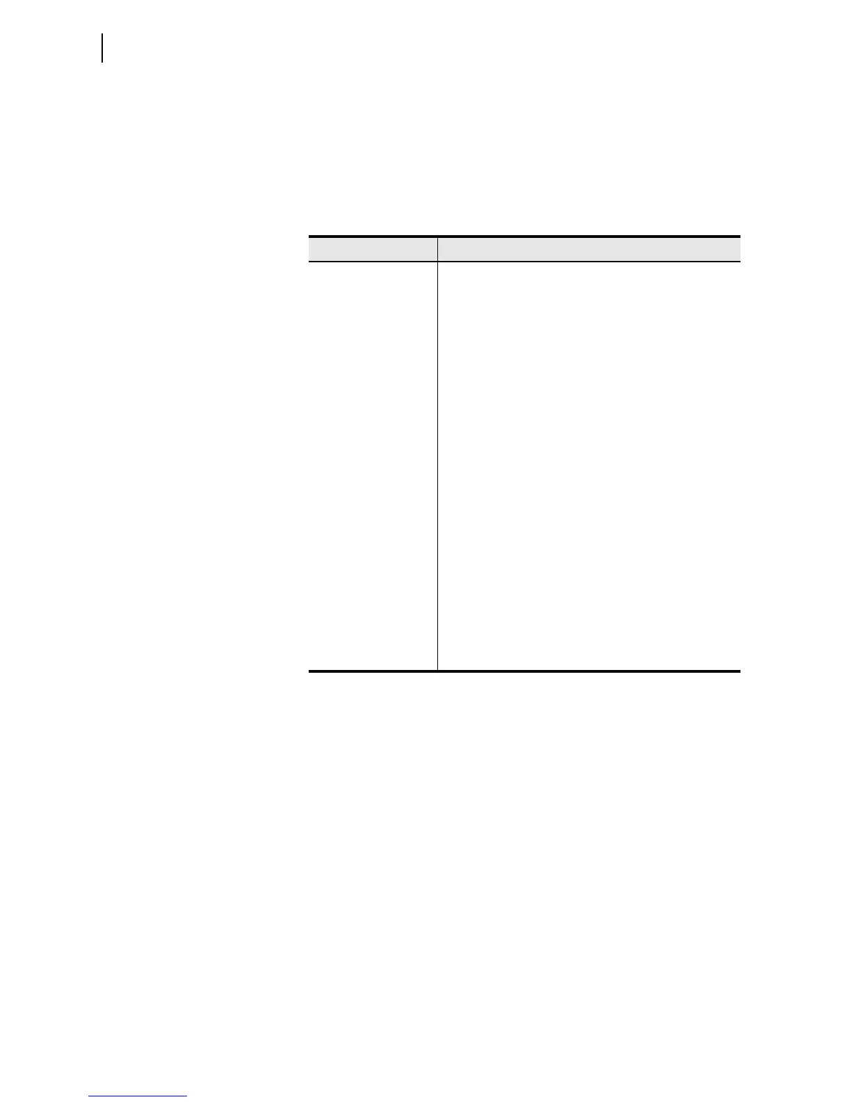
Table 2.1 Pinout of Control Connector for Full-Size Enclosures With the
Combined Sensor Connector
Pin Number Description
A 120 Vac Control Power Transformer
B Control Power Transformer Neutral
C Open A-Phase
DClose A-Phase
E Reserved
F Open B-Phase
G Close B-Phase
H Reserved
J Open C-Phase
KClose C-Phase
L Reserved
M A-Phase 52a Auxiliary Contact
N A-Phase 52b Auxiliary Contact
P B-Phase 52a Auxiliary Contact
R B-Phase 52b Auxiliary Contact
S C-Phase 52a Auxiliary Contact
T C-Phase 52b Auxiliary Contact
U Reserved
V Reserved
 Loading...