Index
Derating............................................................... 12
Derating depending on
Ambient temperature.................................... 308
Installation altitude.......................... 35, 295, 308
The rotating field frequency.......................... 295
Derating factors ................................................. 308
Description of mounting positions ..................... 331
Determining the operating hours ....................... 263
Device
Disposing of.................................................. 262
Installing ......................................................... 31
Mounting......................................................... 36
Mounting with spacers.................................... 38
Replacing ..................................................... 258
Device replacement........................................... 255
Device structure
Cable entry positions...................................... 16
Connection unit nameplate............................. 28
Electronics...................................................... 23
Electronics nameplate .................................... 26
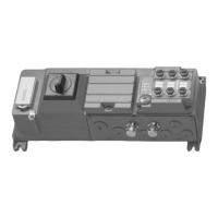
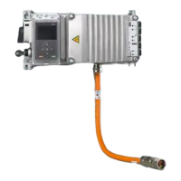
MOVIMOT
®
flexible MMF1. ............................ 14
Nameplate device........................................... 18
Nameplate plug connector positions .............. 21
Nameplate positions....................................... 17
Diagnostics
Fault messages ............................................ 190
LED displays ................................................ 195
MOVISUITE
®
................................................ 190
Digital inputs...................................................... 309
Dimension drawings
BS-005 protective grid.................................. 318
BW100-005/K-1.5......................................... 318
BW100-009-T ............................................... 320
BW150-003/K-1.5......................................... 317
BW150-006-T ............................................... 319
Device .................................................. 332, 334
Device with cooling fins ........................ 333, 335
Line choke .................................................... 326
Spacer .......................................................... 341
Dimension drawings of plug connectors
At the electronics cover ................................ 336
In the connection box ................................... 337
DIP switch
Description ................................................... 144
Drive selection................................................... 272
DynaStop
®
......................................................... 181
Disabling for the startup procedure .............. 164
Functional description .................................. 181
In connection with STO ................................ 184
E
EAC ................................................................... 302
Easy mode ........................................................ 137
Electrical installation............................................ 12
Safety notes ................................................... 12
Electronics
Connection box .............................................. 23
Electronics cover (inside) ............................... 23
Electronics cover (outside) ............................. 25
Nameplate ...................................................... 26
Type designation ............................................ 26
Electronics cover
Inside.............................................................. 23
Minimum installation clearance ...................... 33
Mounting......................................................... 32
Outside ........................................................... 25
Removing ....................................................... 34
Electronics data................................................. 311
Embedded safety notes......................................... 7
EMC..................................................................... 44
EMC cable glands
Cable shielding............................................... 73
Installation ...................................................... 73
Overview ...................................................... 327
Encoder
AZ1Z............................................................. 312
Technical data .............................................. 312
Equipotential bonding.......................................... 45
At the connection box (option)........................ 48
Error
Switch-off responses .................................... 191
Ethernet cable
Cable routing .................................................. 68
Cable selection............................................... 68
Cable shielding............................................... 68
Expert mode ...................................................... 137
Extended storage .............................................. 260
F
Fault
Fault messages .................................... 190, 192
29129451/EN – 12/19
Operating Instructions – MOVIMOT
®
flexible
360
 Loading...