Chapter 3 Operating Instructions
CLV 42x bar code scanner
3-6 © SICK AG · Division Auto Ident · Germany · All rights reserved 8 009 981/O078/16-08-2004
Product description
3.2 Method of operation
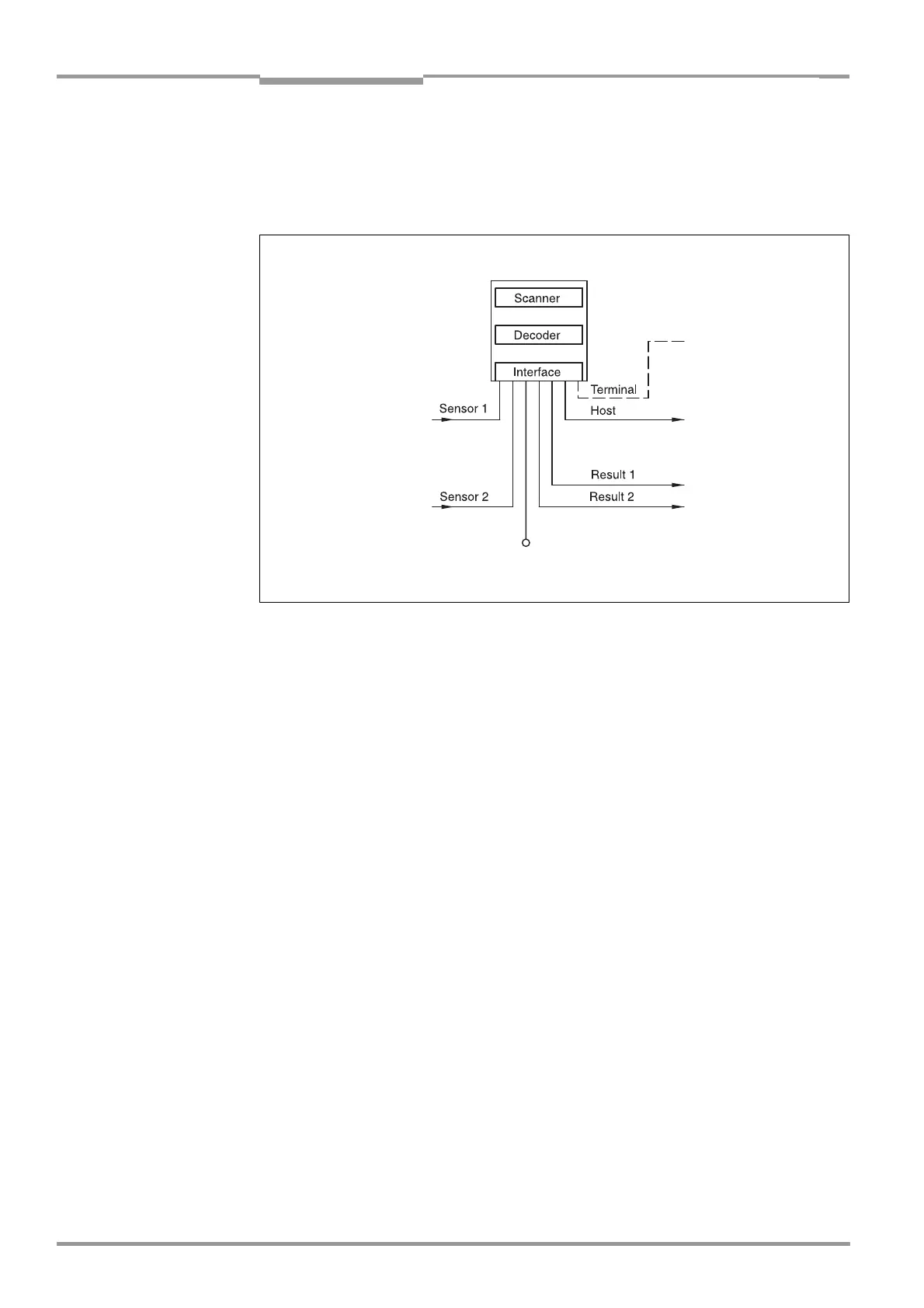
The CLV first scans the bar code with a scan line and then decodes it. The CLV forwards the
data via the serial host interface (main data interface) to a host/PC for further processing.
An overview of the CLV functions is provided in
Fig. 3-2.
The tried and tested standard decoder of the CLV series is available for decoding.
The CLV derives useful diagnosis data from the reading process and transfers it to the host.
It also records operating data that can be interrogated at any time. The quality of the read
can be checked in "Percentage Evaluation" mode.
To start a reading process when an object is located in the reading field, the CLV requires a
suitable trigger. This opens a time window ("reading interval") in the CLV for the reading
procedure. In the default setting, this trigger is supplied by an external reading pulse sensor.
Alternative trigger sources include reflector polling, free-running mode or a command via the
host interface.
The current operating status is indicated by four LEDs.
A beeper indicates the status of the reading result. In the default setting, the "Good Read"
function is selected for this.
If the trigger is supplied externally by a sensor, the "Sensor 1" switching input signals the
start of the reading procedure to the CLV. The "Sensor 2" switching input can be used to
teach in a match code. The "Result 1" and "Result 2" switching outputs can be assigned
various functions and trigger external devices, such as a PLC.
The CLV is operated and configured via the serial terminal interface (auxiliary interface) using
the "CLV Setup" software or via the host/terminal interface and command strings.
System messages, warnings and error messages help you with configuration and with
locating the source of errors during startup and in reading mode.
Fig. 3-2: Block diagram: CLV functions
Signal
Teach-in match code 1
Path increment
End of reading interval
DC 10 to 30 V
PC
Operation
Parameterizing, etc.
HOST
Further processing
of the reading result
Status indicator
e. g. Good Read
e. g. No Read
CLV 42x
Photoelectric switch
Reading pulse