Chapter 5 Operating Instructions
CLV 42x bar code scanner
5-4 © SICK AG · Division Auto Ident · Germany · All rights reserved 8 009 981/O078/16-08-2004
Electrical connection
5.4.3 Non-SICK power pack/connections without the SICK connection module
If a non-SICK power supply unit is used instead of the CDB 420 or CDM 420, it must provide
a functional extra-low voltage in accordance with the standard IEC
364-4-41 and a
continuous power output of at least 4 W.
The output circuit must be reliably electrically isolated from the input circuit. Do do so,
use a safety isolating transformer pursuant to IEC
742.
The minimum wire cross-section for the power supply (pin 1/pin 5) is 0.15 mm
2
(approx.
26 AWG).
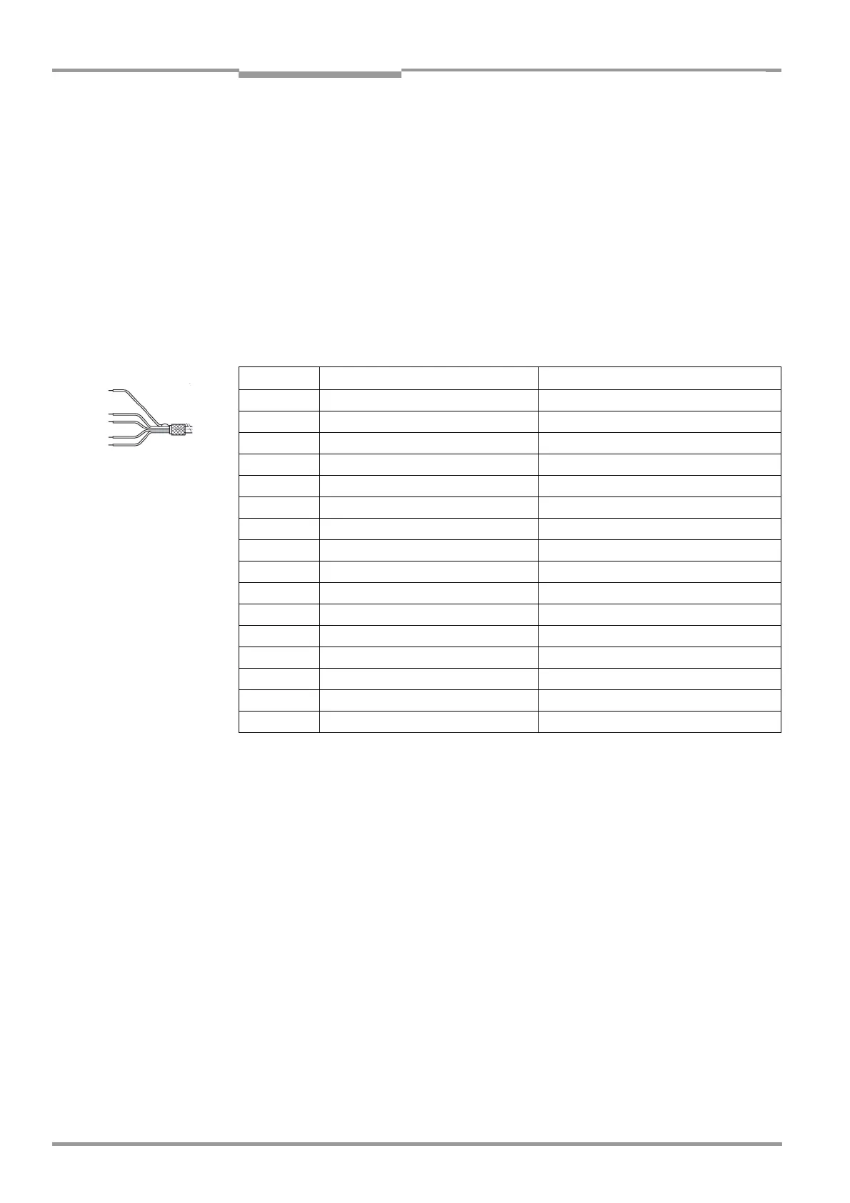
Use the cable no. 6 010 137 with 15-pin D Sub HD socket and open wire ends to
connect the CLV. The color assignment of the wires is shown in
Table 5-4.
Note The CLV 42x is UL certificated when a class 2 power supply according to UL 1310 is used.
5.5 Making electrical connections
5.5.1 Overview of connection procedure
• Connect the power supply
• Connect the host interface
• Connect the PC (connect the terminal interface)
• Connect switching input "Sensor 1" and, if necessary, "Sensor 2" as well
• Connect switching outputs "Result 1" and "Result 2"
5.5.2 Auxiliaries
• Tools
• Digital measuring device (current/voltage measurement)
Pin Signal Wiring color
1 10 to 30 V DC red
2 RxD (Terminal) purple
3 TxD (Terminal) yellow
4 Sensor 2 red/black
5 GND black
6 RD+ (RS 422/485) light blue
7 RD– (RS 422/485); RxD (RS 232) blue
8 TD+ (RS 422/485) turquoise
9 TD– (RS 422/485); TxD (RS 232) green
10 CAN H gray
11 CAN L pink
12 Result 1 brown
13 Result 2 orange
14 Sensor 1 white
15 SensGND white/black
– Shield white/green
Table 5-4: Wiring color assignment of cable no. 6 010 137 (open end)