Operating Instructions Chapter 5
CLV 42x bar code scanner
Electrical connection
8 009 981/O078/16-08-2004 © SICK AG · Division Auto Ident · Germany · All rights reserved 5-5
5.5.3 Connecting the power supply
If the CLV is powered via the CDB 420 or CDM 420 connection module, the power supply
does not have to be wired separately.
1. Ensure that the power supply to the CDB 420 or CDM 420 is switched off.
2. Connect the 15-pin plug on the CLV to the corresponding socket on the CDB 420 or
CDM 420
and screw it tightly. The connection cable can be extended by 2 m (6.56 ft)
using the extension cable no. 6 010 075.
The data and function interfaces of the CLV are connected to the connection module.
– or –
External power pack:
Connect the power supply to the red wire (pin 1, +10 to +30 V DC) and the black wire
(pin 5, GND) of cable no. 6 010 137. (See
also Table 5-4.)
5.5.4 Connecting the host interface
Risk of damage to the interface module
Electronic components in the CLV may be damaged if the host interface is connected
incorrectly.
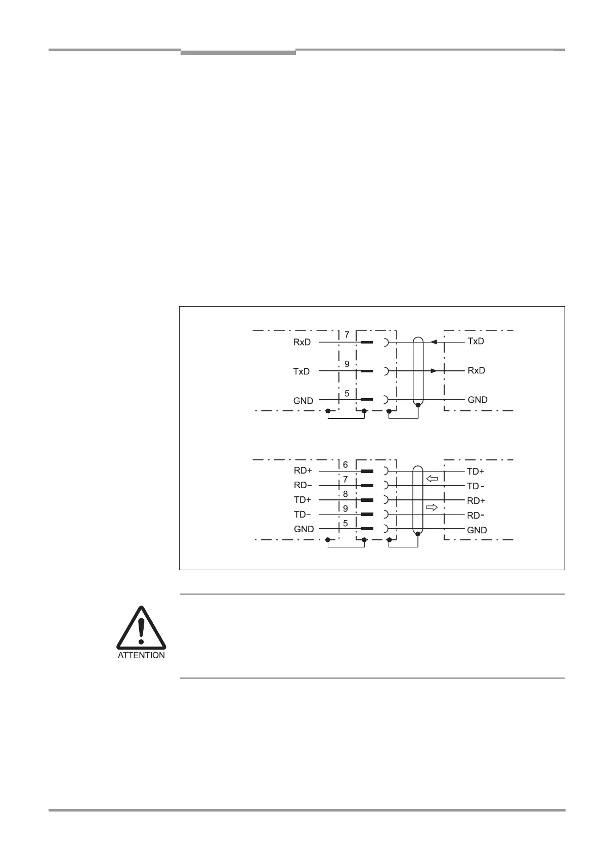
Connect the host interface as shown in Fig. 5-2.
Check the connections carefully before you switch on the CLV.
Connect the host interface on the CLV to the host using shielded cables (EMC
requirements). Ensure that the maximum cable lengths are not exceeded (
Table 5-2,
Page 5-3).
Fig. 5-2: Connections of the host interface
CLV 42x
Host
Host
CLV 42x
RS 232
RS 422
( )= 9-pin D Sub
plug at PC