Operating Instructions Chapter 5
CLV 42x bar code scanner
Electrical connection
8 009 981/O078/16-08-2004 © SICK AG · Division Auto Ident · Germany · All rights reserved 5-7
5.5.6 Connecting the PC
The CLV is operated and configured with the"CLV Setup" program. In order to do so, you
must connect the device to the PC via the terminal interface (auxiliary interface). Unlike the
host interface, the terminal interface has a permanent data format and a fixed data transfer
rate.
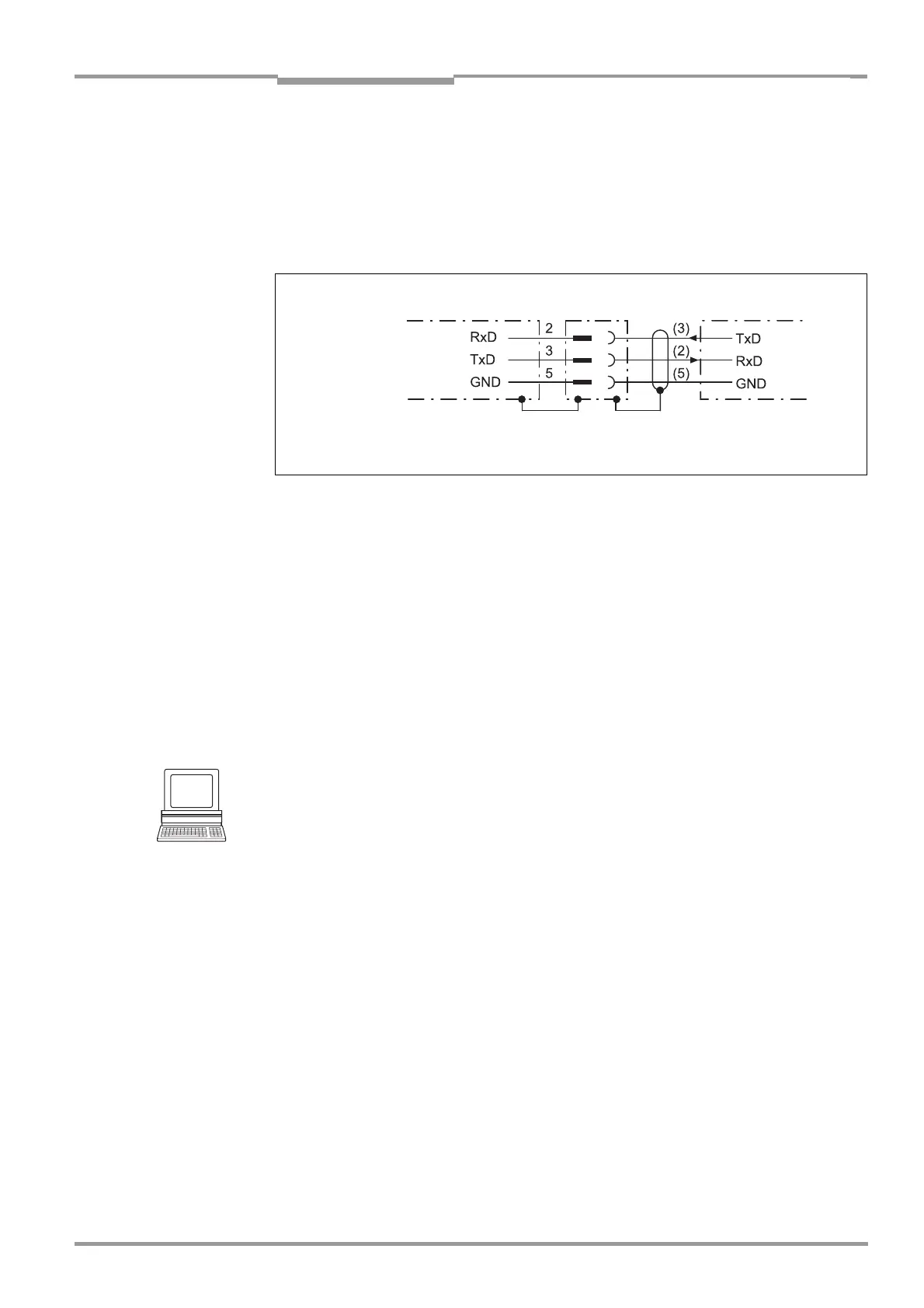
Fig. 5-3 shows how the terminal interface is connected. The cable length is not to
exceed 10 m (32.8 ft).
1. Switch off the PC and power supply to the SICK connection module.
2. Connect the PC to the internal, 9-pin ”Aux" plug of the connection module.
Use a 3-core RS 232 data cable (null modem cable) for this purpose, e. g.
no. 2 014 054 (RxD and TxD crossed).
– or –
If a non-SICK connection module is used:
Connect the PC as shown in Fig. 5-3.
3. Switch on the PC and power supply to the SICK connection module.
4. Set the communication parameters (see Chapter 10.4.3 Starting "CLV Setup",
Page 10-10).
Tip
In the default setting, the terminal interface outputs the reading result in "Reading
Diagnosis" mode.
You can change the operating mode to "Monitor Host Interface", "Auxiliary Input" or
“External Data String Input“ on the
AUXILIARY INTERFACE tab in the CLV Setup program.
Fig. 5-3: Connections of the terminal interface
PC
RS 232
CLV 42x
( )= 9-pin D Sub
plug at PC