Chapter 5 Operating Instructions
CLV 42x bar code scanner
5-10 © SICK AG · Division Auto Ident · Germany · All rights reserved 8 009 981/O078/16-08-2004
Electrical connection
For connecting the switching outputs via the CDB 420 or CDM 420 Connection Module, see
the “CDB 420 Connection Module“ Operating Instructions (order no.
8 010 001,
German/English version) respectively the “CDM 420 Connection Module“ Operating
Instructions (order no.
8 010 004, German/English version).
Note If the "Device Ready" function is chosen, the CLV outputs a static pulse in Reading mode.
Tip
The output function, pulse duration (timer) and polarity of the signals can be changed on the
DEVICE CONFIGURATION tab in the CLV Setup program.
Click the RESULT OUTPUT PARAMETERS button. Edit dialog box.
Download all changes to CLV.
Recommendation To check the switching functions using a high-impedance digital voltmeter, power the
outputs.
This prevents incorrect voltage values/switching statuses from being displayed.
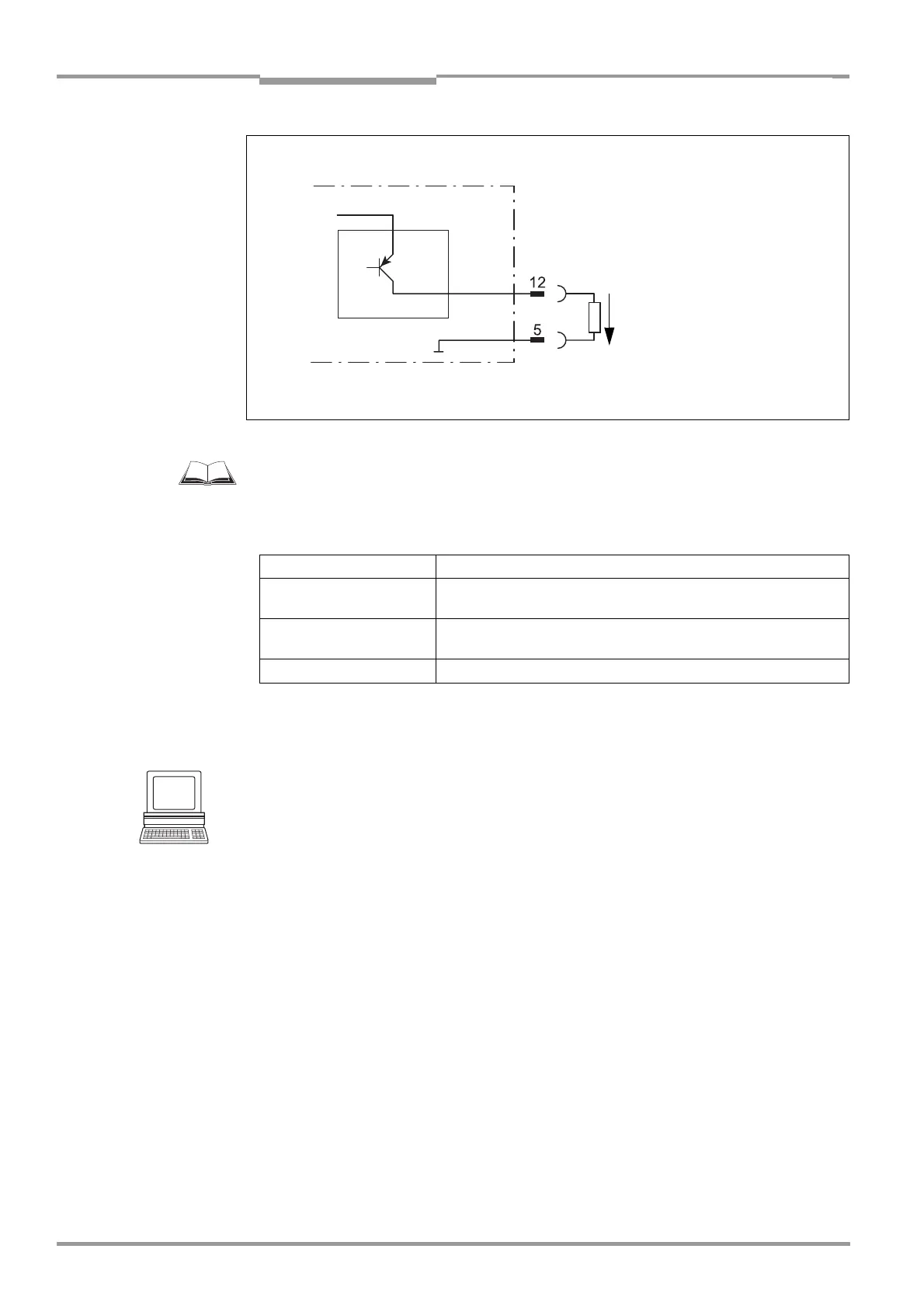
Fig. 5-6: Connections of the "Result 1" switching output
V
S
CLV 42x
"Result 1"
V
S
= + 10 to +30 V DC
Pulse duration
based on setting:
– 10 ms to 990 ms
–00: static
(to the end of the
next reading pulse)
Structure of output
Result 2 (pin 13)
same as output Result 1
V
o
Switching mode PNP-switching with respect to the power supply V
S
Characteristics short-circuit-proof + temperature-protected,
not electrically isolated from V
S
Function assignment
(default setting)
Result 1: "Device Ready (static)", polarity: not inverted
Result 2: "Good Read" (100 ms), polarity: not inverted
Electrical values 0 V ≤ V
o
≤ V
S
Guaranteed: (V
S
−1.5 V) ≤ V
o
≤ V
S
at I
o
≤ 100 mA
Table 5-7: Characteristic data of the "Result 1" and "Result 2" switching outputs