Operating Instructions Chapter 5
CLV 42x bar code scanner
Electrical connection
8 009 981/O078/16-08-2004 © SICK AG · Division Auto Ident · Germany · All rights reserved 5-9
The "Teach-in match code" function is selected in the default setting.
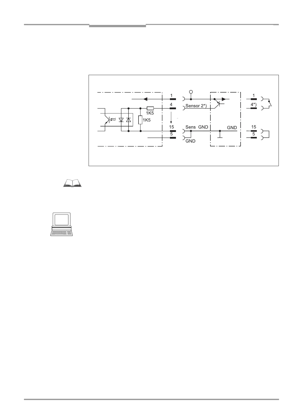
The characteristic data is identical to that for the "Sensor 1" input (Table 5-6).
Fig. 5-5 shows the connections of the switching input.
Connect the sensors as is shown in Fig. 5-5.
For connecting the switching input via the CDB 420 or CDM 420 Connection Module, see
the “CDB 420 Connection Module“ Operating Instructions (order no.
8 010 001,
German/English version) respectively the “CDM 420 Connection Module“ Operating
Instructions (order no.
8 010 004, German/English version).
Tip
The function assigned to the "Sensor 2" input can be modified on the DEVICE CONFIGURATION
tab in the CLV Setup program.
Click the FUNCTION SENSOR 2 drop-down list and choose the required function.
Download all changes to CLV.
The connections and procedure for teaching in match code 1 are described in
Chapter 10.9.1 Triggering the teach-in match code 1 via the "Sensor 2" switching input,
Page 10-26.
5.5.9 Connecting the "Result 1" and "Result 2" switching outputs
The two switching outputs can be assigned different functions for outputting result statuses
independently of each other. If the assigned event occurs during the reading procedure, the
corresponding switching output becomes live at the end of the reading pulse for the
selected pulse duration. The pulse duration is identical for both outputs.
The "Result" LED is linked to the "Result 2" output and lights up in "Reading" mode for the
selected pulse duration and function of the result status display (default setting: "Good
Read", 100 ms).
Fig. 5-6, Page 5-10 shows an example of how the "Result 1" switching output can be
connected. Table 5-7 describes the characteristic data for the outputs. This data is identical
for both outputs.
Connect the outputs as shown in Fig. 5-6.
Fig. 5-5: Connections of the "Sensor 2" switching input
CLV 42x V
S
PNP sensor Switch
V
S
= +10 to +30 V DC *) V
imax
= 28 V!
V
S
V
S
V
i