GM35 Operating Instructions
Probe Model
Commissioning
56 © SICK MAIHAK GmbH • Germany · All rights reserved 8009389/07-2006
‡ Connect the short hose piece on the differential pressure monitor securely to the purge-
air gland on the GMP measuring probe using the hose clamp.
‡ Connect the two 6.3 mm tab receptacles of the installed signal cable to terminals 2 and
3 (NO and COM, NC contact) on the differential pressure monitor.
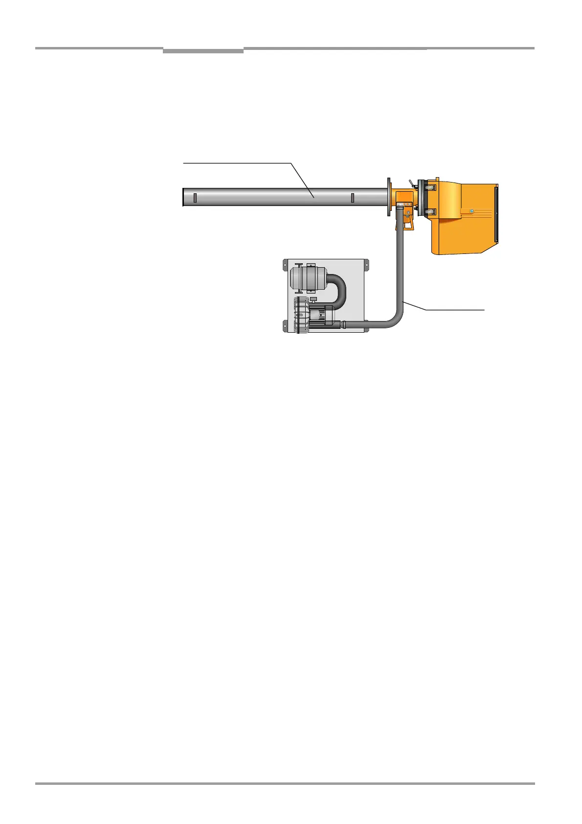
Fig. 30 Connecting the purge-air unit with the optional differential pressure monitor
Connecting the purge-air supply to the SR unit
‡ Position the SR unit with measuring probe in the immediate vicinity of the flange with pipe
mounted on the measurement gas duct to connect the purge-air hose and insert the
measuring system in the duct while the purge-air supply is running.
If the angle flange, art. no. 2 017 833, was used to adjust the system, the measuring sys-
tem is usually already located at the duct flange.
‡ Switch on the power supply to the purge-air unit briefly to test whether it is functioning
correctly, and remove any dust that may have entered the purge-air hose.
‡ Connect the purge-air hose from the purge-air unit to the purge-air gland on the measur-
ing probe using a hose clamp. If you are using a differential pressure monitor, connect
the hose to it (see Fig. 30).
‡ Switch on the purge-air supply.
The purge-air supply is now activated and protects the measuring system from dirt and over-
heating. For this reason, the purge-air supply must never be switched off while the measur-
ing probe is inside the measurement gas duct.
‡ If you have not already done so, attach visible warnings to all of the switch devices that
can switch off the purge-air supply to prevent it from being deactivated inadvertently.
6.5.2 GPP measuring probes: power supply
If you are using a GPP measuring probe, the optical boundary surfaces must be heated to
the necessary operating temperature before the measuring probe is inserted in the duct:
‡ Connect the GPP measuring probe to the power supply.
If the power supply cable of the measuring probe that is to be used for continuous mea-
suring operation cannot be connected while the measuring probe is not yet inserted in
the duct, or if it cannot be switched on, use a temporary power supply cable similar to the
one you may have used for the zero-point adjustment (Page page 54).
Purge-air hose
GMP measuring probe
Purge-air unit

 Loading...


