Start-up and Parameter Settings
DUSTHUNTER T · Operating Instructions · 8012428 V 2.0 · © SICK MAIHAK GmbH Germany 57
4.2 Application specific settings
The measuring system must first be set to the respective internal duct diameter to ensure
correct measurement. The following steps are required:
● Focussing the sender light beam
The light spot on the reflector must lie within the optical active reflection surface under
consideration of the active measuring path and the swivel angle allowed.
● Scaling the measuring system to a path free of particles
Influences on measuring results specific to the device and dependent on the distance
must be eliminated. The path free from particles must be identical to the active mea-
suring path (distances between the optical surfaces of the sender/receiver unit and
reflector must be the same).
4.2.1 Preparatory work
b
Assemble the measuring system away from the installation location according to Fig. 41
(the electrical connection between MCU - sender/receiver unit and sender/receiver unit
- reflector (only on DUSTHUNTER T200) must be ensured).
There are two options here:
–Using the optional adjusting holder (
→
p. 120, §7.3.7)
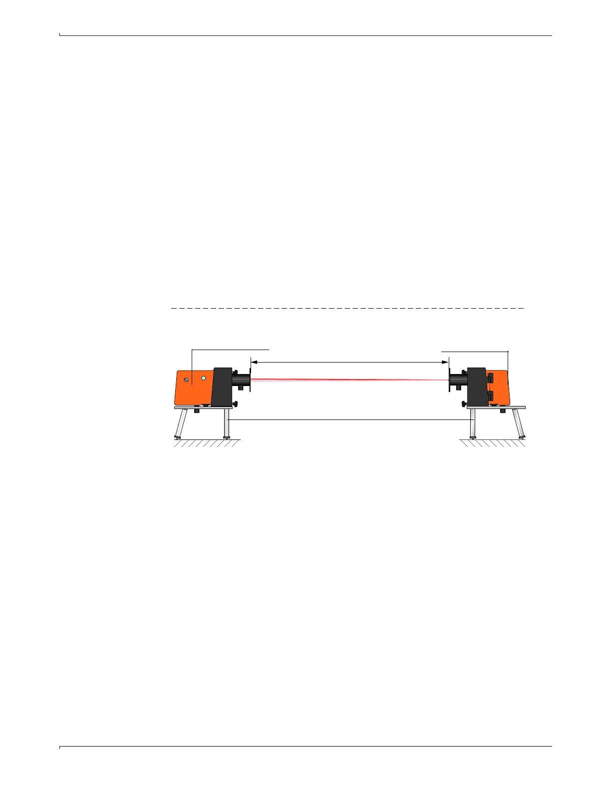
Figure 41 Creating a smoke-free path with adjusting stands
A
A =distance flange - flange
Adjusting holder
Sender/receiver unit
Reflector

 Loading...


