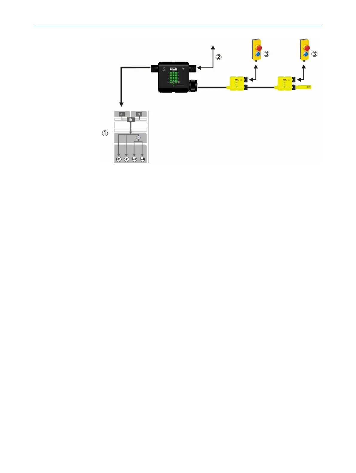
Figure 8: I/O functions of the Flexi Loop MSTR2 accessory
1
Program in Flexi Classic
2
I/O functions
3
Emergency stop pushbutton with reset button and Reset required lamp
In the configuration from the factory the AUX_IN of the MSTR2 Flexi Loop accessory
switc
hes all AUX_OUT of the Flexi Loop nodes. The AUX_IN of the Flexi Loop nodes
switch the AUX_OUT of the MSTR2 Flexi Loop accessory.
The non-safe input of the MSTR2 Flexi-Loop accessory switches the non-safe outputs of
the Flexi Loop nodes. You can use this function, for example, to control lamps or to
implement a locking device.
The non-safe output of the Flexi Loop MSTR2 accessory collects the statuses of the
non-safe inputs of the Flexi Loop nodes. The statuses are linked with a logical OR oper‐
ation prior to delivery (factory setting). You can use this function for a group reset sig‐
nal, for example.
The factory settings for the MSTR2 Flexi Loop accessory can be configured via IO-Link.
IO-Link functions of the MSTR2 Flexi Loop accessory
If t
he IO-Link is connected, for example, to a PLC, then the MSTR2 Flexi Loop accessory
and the PLC exchange data via this interface.
3 PR
ODUCT DESCRIPTION
18
O P E R A T I N G I N S T R U C T I O N S | Flexi Loop 8015836/YT10/2016-05-24 | SICK
Subject to change without notice