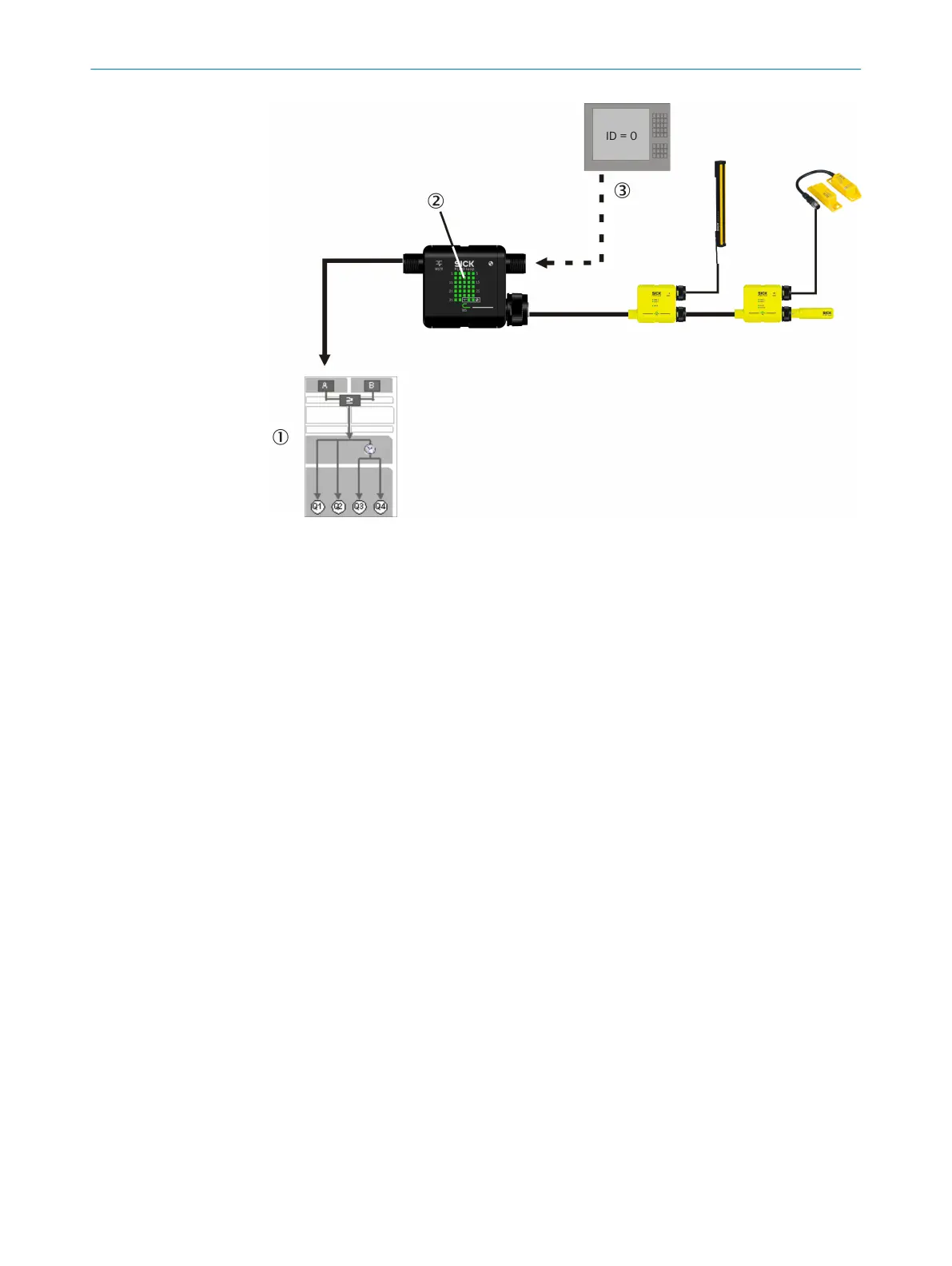
Figure 9: IO-Link functions of the MSTR2 Flexi Loop accessory
1
Program in Flexi Classic
2
LED display
3
Diagnostics information on the PLC
The parameter list with all data that can be read and written is available as a separate
document (SIC
K part number 8017450).
Process data
The PLC and the MSTR2 Flexi Loop accessory communicate cyclically in a data frame
for process data:
•
Flexi Loop transmits 4 bytes of input data to the PLC. These bytes contain the sta‐
tus of the non-safe inputs AUX_IN of the Flexi Loop nodes.
•
Flexi Loop receives 4 byte of output data from the PLC. These bytes contain the
commands for the non-safe outputs AUX_OUT of the Flexi Loop nodes.
Service data
The PLC communicates acyclically with the MSTR2 Flexi Loop accessory for service
data. The service data offer the following options:
•
execution of commands
•
configuration of the parameters for the Flexi-Loop string and the individual Flexi
Loop nodes
•
reading the parameter values and statuses of the Flexi Loop string and the Flexi
Loop nodes
Events
While in operation you can follow occurrences in the system via so-called events. The
following events are available:
•
state of the cut-off path
•
synchronization safety controller
•
Flexi Loop not in operation
•
cable connection
•
dynamic error
PRODUCT DESCRIPTION 3
8015836/YT10/2016-05-24 | SICK O P E R A T I N G I N S T R U C T I O N S | Flexi Loop
19
Subject to change without notice