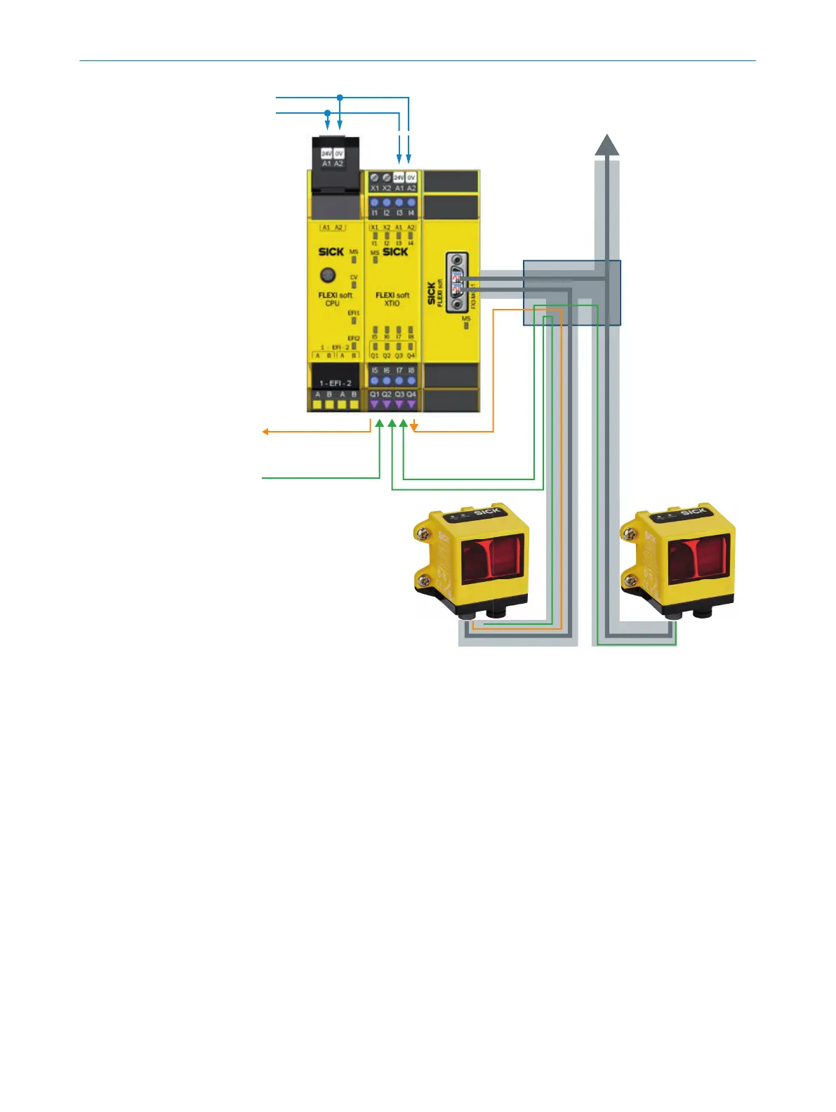
DV
Safe outputs
Output:
Test request at OLM 2
Inputs: Test signal
“Forward/Reverse”
Inputs: Sensor IDs
+24V =
SSI signals from OLM 1 to
process control
(open cable end)
X connector
Preassembled cable
with SSI signal splitter
OLM 2 OLM 1
Linear measurement sensor
OLM100 Hi
(with sign-of-life test)
Linear measurement sensor
OLM100 Hi
Figure 4: Wiring principle
F
rom the connector plug on the FX3-MOC1 to the SSI signal splitter, the X-junction must
be contained within an electrical installation area.
OLM 1 and OLM 2 are numbered when the X-junction is connected. The connector plug
for the OLM 2 has a colored mark and must be connected to the linear measurement
sensor for which the bar code tape displays a higher position value. The connector plug
for OLM 1 does not have a mark.
ELECTRICAL INSTALLATION 6
8020941/12O9/2019-08-05 | SICK O P E R A T I N G I N S T R U C T I O N S | Safe Linear Positioning
25
Subject to change without notice