WT34 are photoelectric proximity sensors with background suppression. Depending on the
remission of the object to be detected, and perhaps the background behind it, a minimum
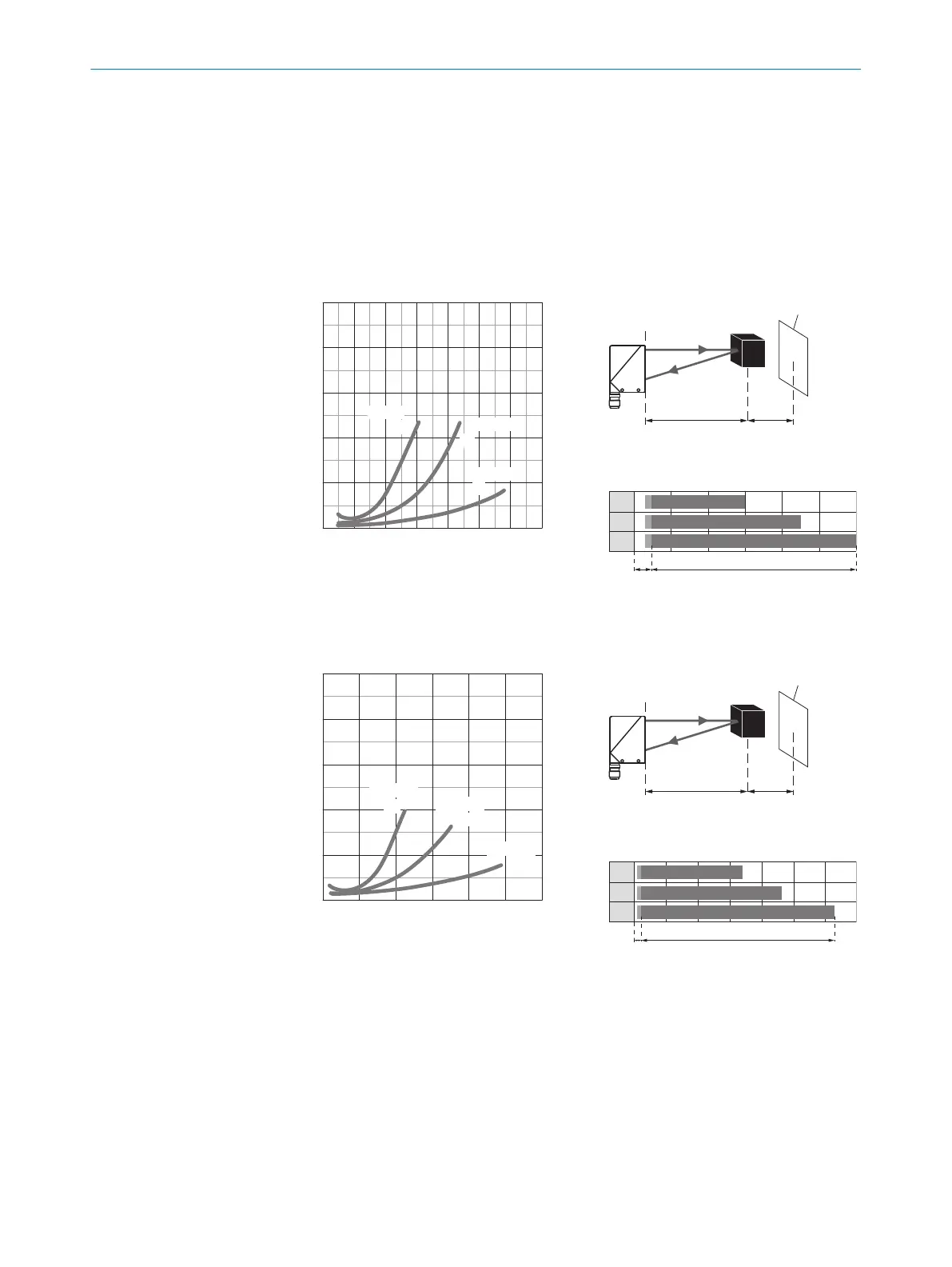
distance (y) between the set sensing range (x) and the background should be maintained.
Remission: 6% = black 1, 18% = gray 2, 90% = white 3 (referring to standard white as
per DIN 5033). We recommend that the adjustment be performed with an object of low
remission.
The minimum distance (= y) for the background suppression can be determined from the
diagram [figure 5 1] as follows:
Example: x = 600 mm, y = 4.5 => 4.5% of 600 mm = 27 mm. That is, the background is
suppressed at a distance of > 627 mm from the sensor.
10
8
6
4
2
0
6%/90%
18%/90%
90%/90%
mm 200 400 600 800 1000 1200 1400
Distance in mm
1
2
3
y
x
Figure 5: WT34-Xx4x, -Xx5x, red light
yx
white back-
ground (90%)
x = 600 mm, y = 27 mm
(= 4.5% of 600 mm)
100 600
100 900
100 1,200
1
2
3
A B
A = Detection distance (depending on
object remission)
B= Adjustment range
10
8
6
4
2
0
6%/90%
18%/90%
90%/90%
mm 500 1000 1500 2000 2500 3000
Distance in mm
1
2
3
y
x
Figure 6: WT34-Xx1x, -Xx2x, infrared
light
yx
white back-
ground (90%)
x = 1,000 mm, y = 30 mm
(= 3% of 1,000 mm)
100 1,300
100 1,800
100 2,500
1
2
3
A B
A = Detection distance (depending on
object remission)
B= Adjustment range
3 Sensing range setting
Sensor with potentiometer: open the sensor cover and protective hood, make sure that no
dirt has gotten into the device.
The sensing range is adjusted with the potentiometer (type: without stop ). Clockwise rota‐
tion: sensing range increased; counterclockwise rotation: sensing range reduced. We rec‐
ommend placing the object within the sensing range, e.g. see table 8. Once the sensing
range has been adjusted, the object is removed from the path of the beam, which causes
the background to be suppressed and the switching output to change [see figure 5 and
figure 6].
COMMISSIONING 8
8009202.11O1 | SICK
Subject to change without notice
11

 Loading...


