4 - 41
MMB-2 Connections and Ratings
Analog device loops 1 and 2
(TB2 and TB3)
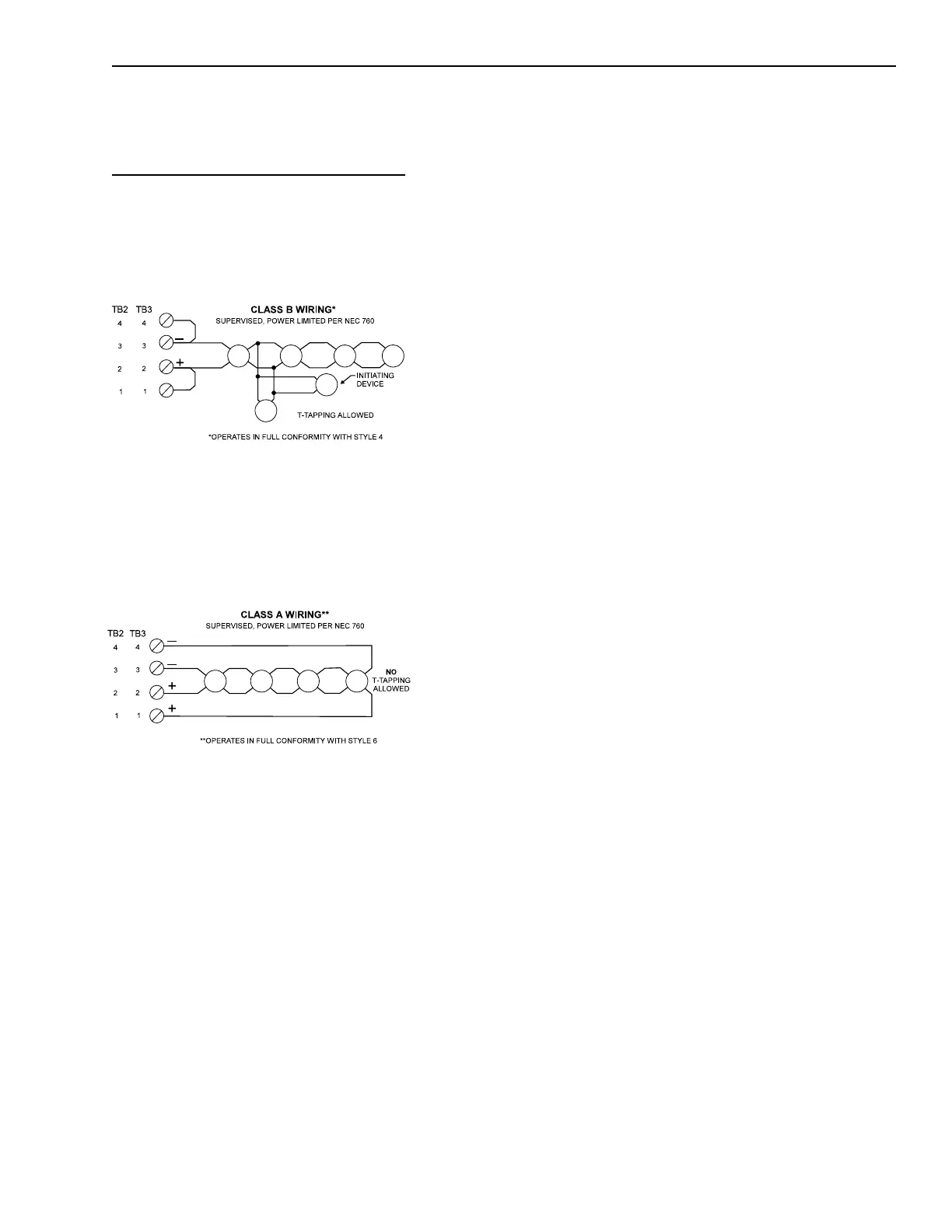
To install a device for Class B, refer to
the wiring diagram below and the
electrical ratings.
Wiring the Analog Loops
Class A Wiring
Wiring the Analog Loops
Class B Wiring
NOTES
1. Power limited to
NFPA 70 per NEC 760.
2. Each detector or group
of detectors requires
the following:
a 2-wire circuit of 18
AWG minimum
thermoplastic fixture
wire enclosed in a
conduit.
or
18 AWG limited-
energy shielded cable
without conduit, if
permitted by local
building codes.
3. Maximum resistance:
100 ohms total.
4. Maximum
capacitance:
0.4µF between + loop
and loop.
0.8µF between + loop
and chassis.
0.8µF between loop
and chassis.
5. Refer to Wiring Guide
for compatible wire
types.
To install a device for Class A, refer to
the wiring diagram below and the
electrical ratings.
Analog loop electrical ratings:
Supervisory 30 VDC peak
66mA max
Alarm 30 VDC peak
66mA max
(60 devices in alarm)
All wiring must be in accordance with
Article 760 of NEC and the local
building codes.
Only the devices listed in Appendix A,
Table 2 - Analog Addressable Detec-
tors on page A-1 may be used. The UL
identifiers for compatibility are the
same as the model names specified.
6. Maximum voltage:
Supervisory 30 VDC
peak.
Alarm 30 VDC peak.
7. Maximum current:
Supervisory 66mA
Alarm 66mA
8. No end of line device
required.
9. Operates in full
conformance with
Style 4.
10. Operates in full
conformance with
Style 6.
11. Either loop may be
wired Class A or B.
12. 60 devices maximum
per loop.
13. T-tapping is NOT
allowed on Class A
loops.
14. Both circuits are
supervised.
Technical Manuals Online! - http://www.tech-man.com
 Loading...


