4 - 125
ZC1-8B Connections and Ratings
ALL ZONES SUPERVISED, POWER LIMITED
Power Limiting is accomplished using the PLC-4 and
PL864-25A, -70A, or -25S as required
All wiring must be in accordance with Article 760 of
NEC or the local building codes.
Maximum Loop Resistance:
Audio: 25.2V RMS and 24 VDC
3 ohms max, 37.5 watts (1.5A)
2.5 ohms max, 45 watts (1.8A)
Minimum Wire Size: 14 AWG
Supervisory Speaker Zone Connections
Supervisory: 1.5 VDC, 0.06mA
Activated: 25.2V RMS, 45 watts max (1.8A)
70.7V RMS, 70 watts max (1.0A)
24 VDC, 45 watts max (1.8A)
Maximum Total Load:
For Input 1 (Outputs 1, 2, 3) 25.2V, 3.9A, 100 watts
and Input 2 (Outputs 4, 5, 6) 70.7V, 1.4A, 100 watts
24 VDC, 5.4A, 135 watts
For Input 3 (Outputs 7, 8) 25.2V, 3.6A, 90 watts
70.7V, 1.4A, 100 watts
24 VDC, 3.6A, 90 watts
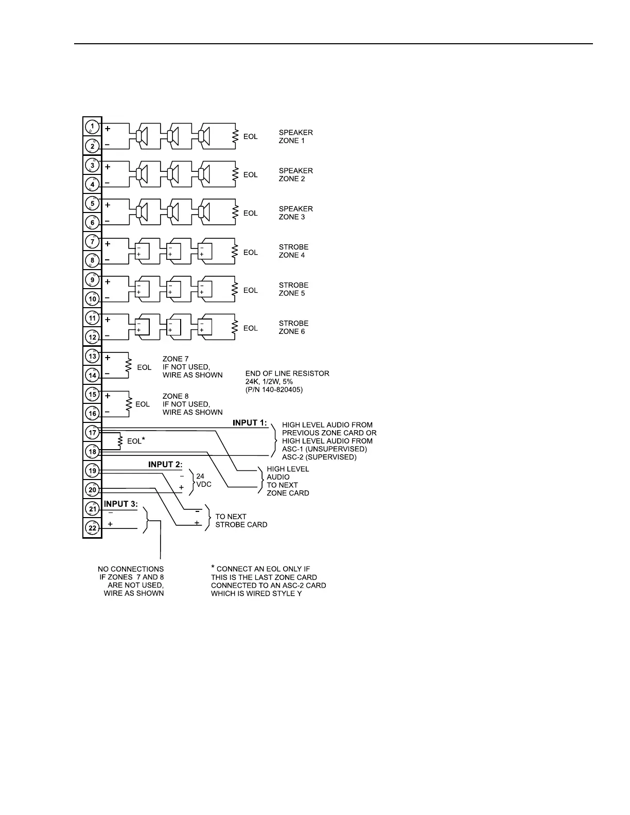
ZC1-8B Combined Speaker Zone and Strobe Wiring Diagram
with a Separate Power Source for Each Input (1, 2, and 3)
NOTE:
ALL STROBE ZONE POLARITIES ARE SHOWN IN
SUPERVISORY CONDITION.
Strobe devices are not polarity supervised and should
be tested in compliance with NFPA Standards.
25/70.7V RMS SPEAKER UNITS and 24 VDC STROBE
UNITS:
Any UL listed Fire Protective Signaling Speaker
rated 25/70.7V RMS may be connected to this
circuit. See Compatible Notification Appliances,
P/N 315-096363 for compatible combination
speaker strobe models.
NOTE:
In combination models, the speakers must be
connected to separate circuits from the strobes.
Technical Manuals Online! - http://www.tech-man.com
 Loading...


