4 - 126
ZC1-8B Connections and Ratings
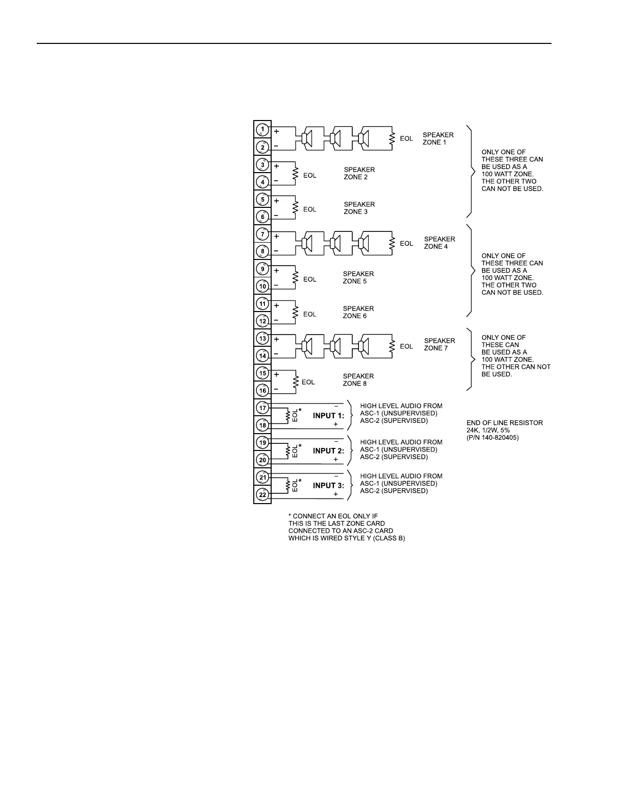
ZC1-8B Speaker Zone Diagram with a Separate 70.7V RMS
Power Source for Each Input (1, 2, and 3)
ALL ZONES SUPERVISED, POWER LIMITED
Power Limiting is accomplished using the PLC-4 and
PL864-25A, -70A, or -25S as required
All wiring must be in accordance with Article 760 of
NEC or the local building codes.
Maximum Loop Resistance:
Audio: 25.2V RMS and 24 VDC
3 ohms max, 37.5 watts (1.5A)
2.5 ohms max, 45 watts (1.8A)
Minimum Wire Size: 14 AWG
Supervisory Speaker Zone Connections
Supervisory: 1.5 VDC, 0.06mA
Activated: 25.2V RMS, 45 watts max (1.8A)
70.7V RMS, 70 watts max (1.0A)
24 VDC, 45 watts max (1.8A)
Maximum Total Load:
For Input 1 (Outputs 1 , 2, 3) 25.2V, 3.9A, 100 watts
and Input 2 (Outputs 4, 5, 6) 70.7V, 1.4A, 100 watts
24 VDC, 5.4A, 135 watts
For Input 3 (Outputs 7, 8) 25.2V, 3.6A, 90 watts
70.7V, 1.4A, 100 watts
24 VDC, 3.6A, 90 watts
NOTE:
Three 2A, 250V fuses (P/N 105-292199) are included in
the fuse kit for applications where zones of up to
100W at 70.7V are required. With separate amplifiers
for each input, one zone per input can be used for this
purpose. Place fuses in the clips for the desired zone
and connect the zone wires to the appropriate
terminals. When these fuses are installed, the EL-410C/D
amplifiers that connect to these zones cannot be used
for any other zones.
70.7V RMS SPEAKER UNITS:
Any UL listed Fire Protective Signaling Speaker
rated 70.7V RMS may be connected to this
circuit. See Compatible Notification Appliances,
P/N 315-096363 for compatible speaker models.
NOTE:
In combination models, the speakers must be
connected to separate circuits from the strobes.
Technical Manuals Online! - http://www.tech-man.com

 Loading...


