Failure and replacement of components during redundant operation
11.1 Failure and replacement of central components
CPU 410-5H Process Automation/CPU 410 SMART
168 System Manual, 10/2013, A5E32631667-AA
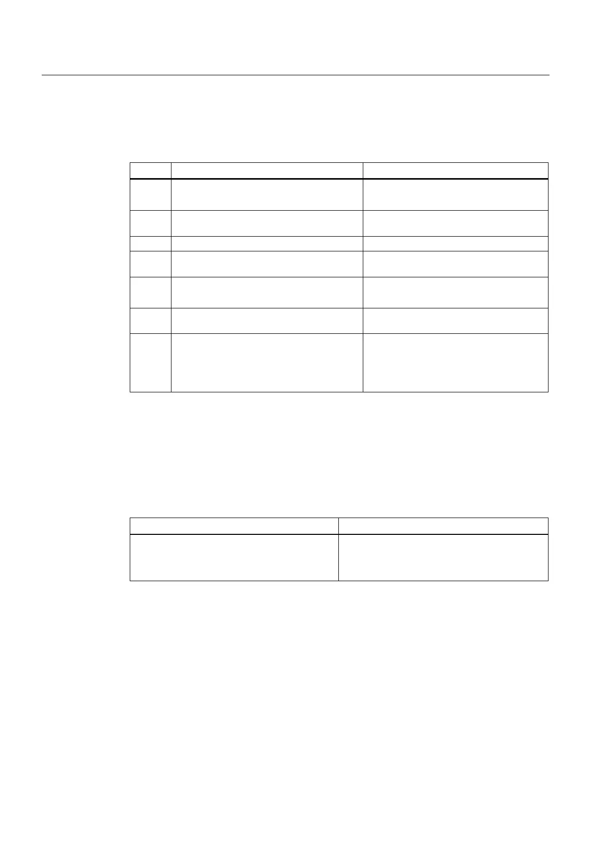
Follow the steps below to
:
How does the system react?
1 Turn off the power supply module.
• The entire subsystem is switched off
(system operates in single mode).
2 Replace the CPU. Make sure the rack
number is set correctly on the CPU.
–
Insert the synchronization modules.
4 Plug in the fiber-optic cable connections of
the synchronization modules.
–
5 Switch the power supply module on again.
• CPU runs the self-tests and changes to
STOP.
6 Perform a CPU memory reset on the
–
7 Start the replaced CPU (for example, STOP-
RUN or Start using the PG).
• The CPU performs an automatic LINK-
UP and UPDATE.
•
The CPU changes to RUN and operates
as the reserve CPU.
Failure and replacement of a power supply module
Starting situation
Both CPUs are in RUN.
How does the system react?
The S7-400H is in redundant system mode and a
power supply module fails.
• The partner CPU switches to single mode.
• The partner CPU reports the event in the
diagnostic buffer and in OB 72.
Proceed as follows to replace a power supply module in the central rack:
 Loading...


