CPU 410-5H Process Automation/CPU 410 SMART
System Manual, 10/2013, A5E32631667-AA
31
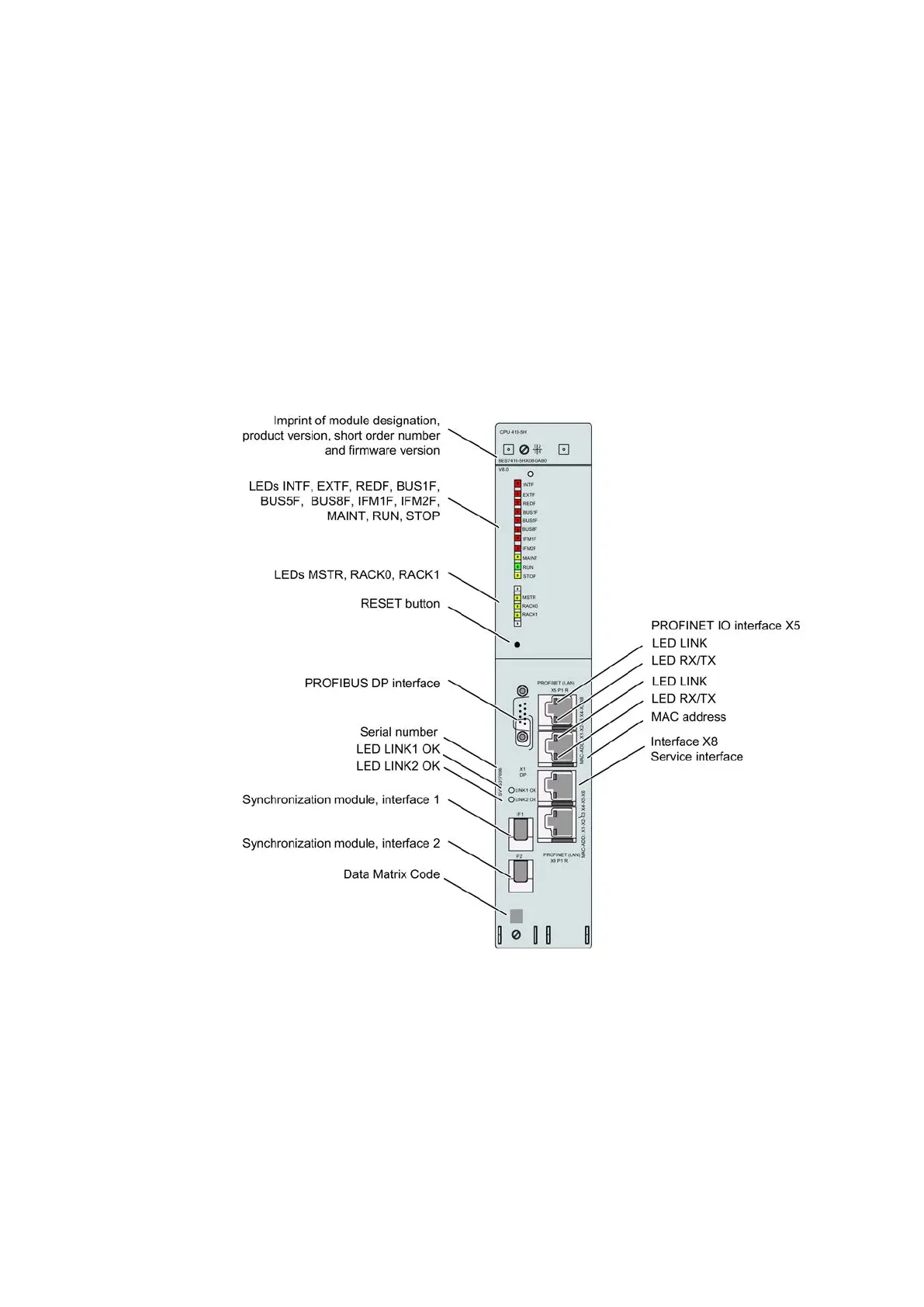
Structure of the CPU 410-5H
Operator controls and display elements on the CPU 410-5H
Operator controls and display elements on the CPU 410-5H
Figure 3-1 Arrangement of the control and display elements on CPU 410-5H
The following table shows an overview of the LED displays on the individual CPUs.
Sections Monitoring functions of the CPU 410-5H (Page 35) and Status and error displays
(Page 37) describe the states and errors/faults indicated by these LEDs.
 Loading...


