Connection examples for redundant I/Os
C.13 SM 326; DI 24 x DC 24 V, 6ES7 326–1BK00–0AB0
CPU 410-5H Process Automation/CPU 410 SMART
System Manual, 10/2013, A5E32631667-AA
319
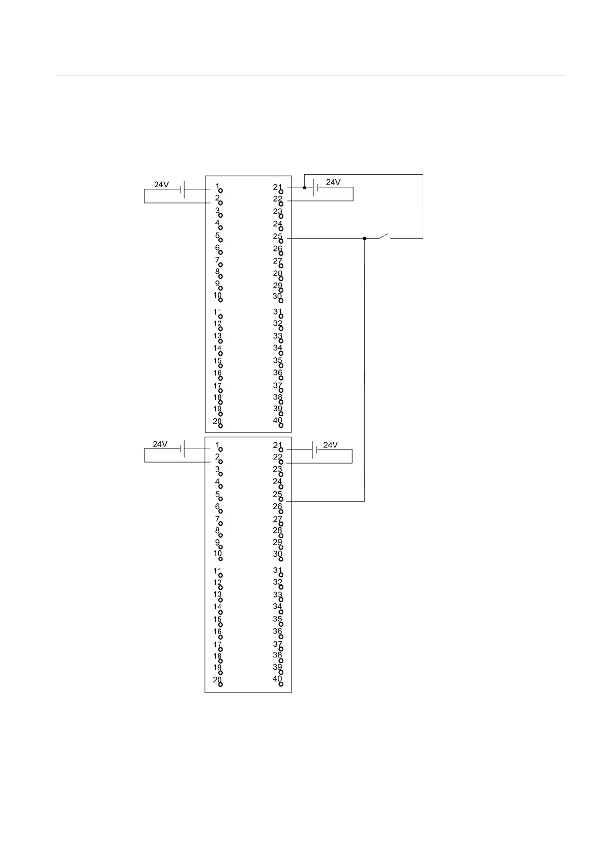
SM 326; DI 24 x DC 24 V, 6ES7 326–1BK00–0AB0
The diagram below shows the connection of one encoder to two redundant SM 326; DI 24 x
DC 24 V. The encoder is connected to channel 13.
Figure C-11 Example of an interconnection with SM 326; DI 24 x DC 24 V
 Loading...


