Failure and replacement of components during redundant operation
11.1 Failure and replacement of central components
CPU 410-5H Process Automation/CPU 410 SMART
172 System Manual, 10/2013, A5E32631667-AA
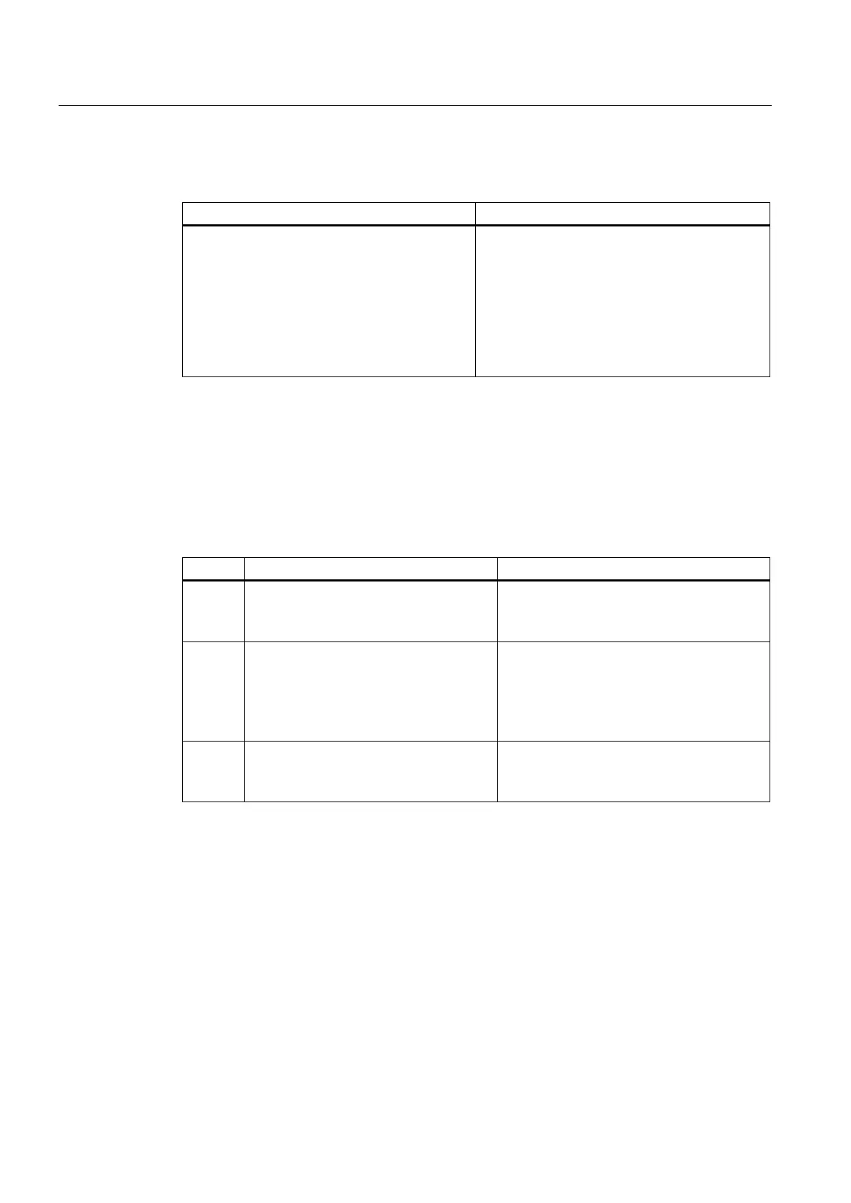
How does the system react?
The S7-400H is in redundant system mode and a
communication module fails.
• Both CPUs report the event in the diagnostic
buffer and via appropriate OBs.
• In communication via standard connections:
Connection failed
• In communication via redundant connections:
Communication is maintained without
interruption over an alternate channel.
If you want to use a communication module that is already being used by another system,
you have to ensure that there are no parameter data saved in the module's integrated
FLASH-EPROM before you swap it.
Proceed as follows to replace a communication module for PROFIBUS or Industrial
Ethernet:
How does the system react?
1 Remove the module.
• Both CPUs process the swapping
interrupt OB 83 synchronized with each
other.
2 Insert the new module.
• Both CPUs process the swapping
interrupt OB 83 synchronized with each
other.
• The module is automatically configured by
the appropriate CPU.
3 Turn the module back on.
• The module resumes communication
(system establishes communication
connection automatically).
Failure and replacement of a synchronization module or fiber-optic cable
In this section, you will see three different error scenarios:
● Failure of a synchronization module or fiber-optic cable
● Successive failure of both synchronization modules or fiber-optic cables
● Simultaneous failure of both synchronization modules or fiber-optic cables
The CPU indicates by means of LEDs and diagnostics whether the lower or upper redundant
link has failed. After the defective parts (fiber-optic cable or synchronization module) have
been replaced, LEDs IFM1F and IFM2F must go out.
 Loading...


