I/O configuration variants
4.7 Connecting redundant I/O to the PROFIBUS DP interface
CPU 410-5H Process Automation/CPU 410 SMART
System Manual, 10/2013, A5E32631667-AA
81
Redundant encoders <-> non-redundant encoders
The table below shows you which analog input modules you can use in redundant operation
with redundant or non-redundant encoders:
Table 4- 5 Analog input modules and encoders
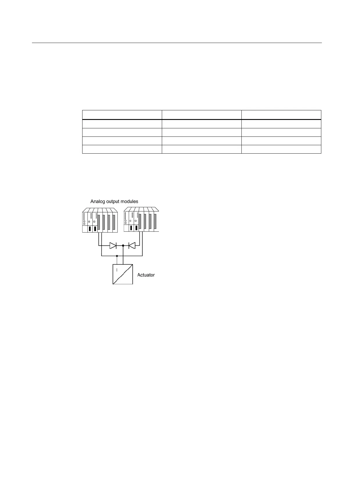
Redundant analog output modules
You implement fault-tolerant control of a final controlling element by wiring two outputs of two
analog output modules in parallel (1-out-of-2 structure).
Figure 4-21 Fault-tolerant analog output modules in 1-out-of-2 configuration
The following applies to the wiring of analog output modules:
● Wire the ground connections in a star structure to avoid output errors (limited common-
mode suppression of the analog output module).
If you do not use terminal modules, see the interconnection examples in the Appendix
Connection examples for redundant I/Os (Page 307)
Only analog output modules with current outputs (0 to 20 mA, 4 to 20 mA) can be operated
redundantly.
 Loading...


